- (01-26) -
MULTI TYPE
2, 3, 4 ROOMS TYPE
MULTI TYPE
2, 3, 4 ROOMS TYPE
INSTALLATION
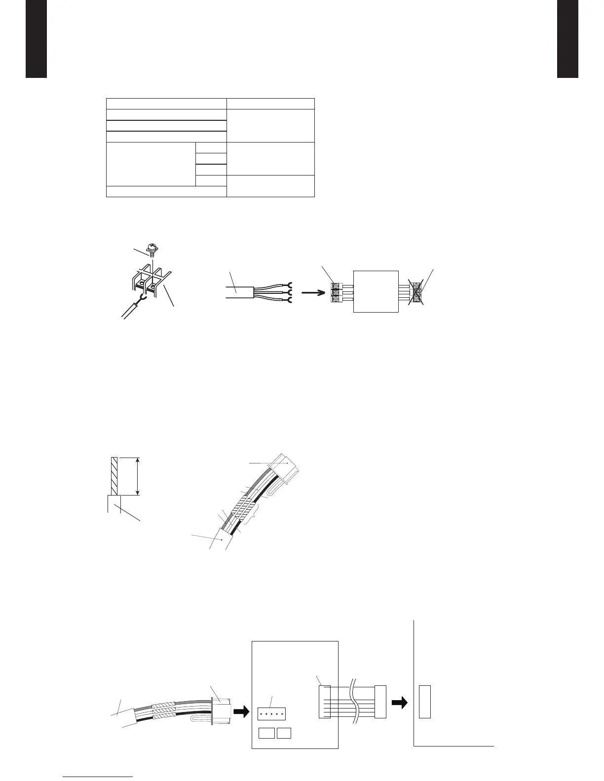
Connection Pattern
z
Note: Connection pattern is different according to type of Indoor unit.
Indoor unit types Connection Pattern
Compact Cassette type
Pattern ASlim Duct type
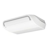
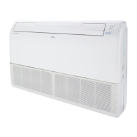
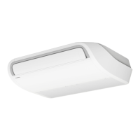
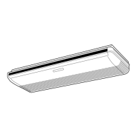
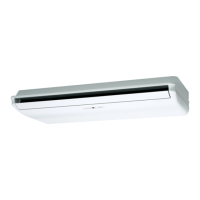
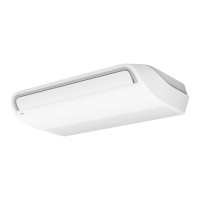
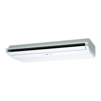
Floor / Ceiling type
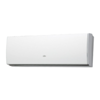
Wall Mounted type
LJ
Pattern BLU
LM
LF
Pattern C
Floor type
Pattern A
z
Connect the end of remote controller cable directly to the exclusive terminal block.
M4 screw
Terminal block
Remote
controller
cable
Remote controller
terminal block
Indoor unit
Outdoor unit /
Power supply
terminal block
Note:
It may be failed if it is connected to the outdoor unit or the terminal block for power
supply.
Pattern B
z
1) Modify the remote controller cable as per below methods.
Use a tool to cut off the terminal on the end of the remote controller cable and then remove
●
the insulation from the cut end of the cable as shown in Fig.
Connect the remote controller cable and connecting cable as shown in Fig.
●
Be sure to insulate the connection between the cables.
●
Remote controller
cable
Connecting
cable
Insulated
connection
Red
Red
White
White
Black
Black
2) Method of connecting remote controller cable
Connecting cable made by above-mentioned 1) is connected with Terminal A of optional
●
communication kit .
Cable connected with Terminal B of communication kit is connected with PCB of Indoor unit.
●
Remote controller
cable
Connecting
cable
Communication kit Indoor unit PCB
Terminal B
Terminal A
A: (CN305)-(LJ type: UTY-XCBXZ1)
(CNC01)-(LU type: UTY-TWBXF)
(CNC01)-(LM type: UTY-XCBXZ2)
B: (CN301)-(LJ type: UTY-XCBXZ1)
(CND01)-(LU type: UTY-TWBXF)
(CNC01)-(LM type: UTY-XCBXZ2)
 Loading...