4
WIRING
All wiring is terminated at the rear of the display unit. The power and transducer cables
must be fitted with a connnector in the field. The water temperature sensor (option) cable
is prefitted with a connector. For detailed information see the interconnection diagram at
the end of this manual.
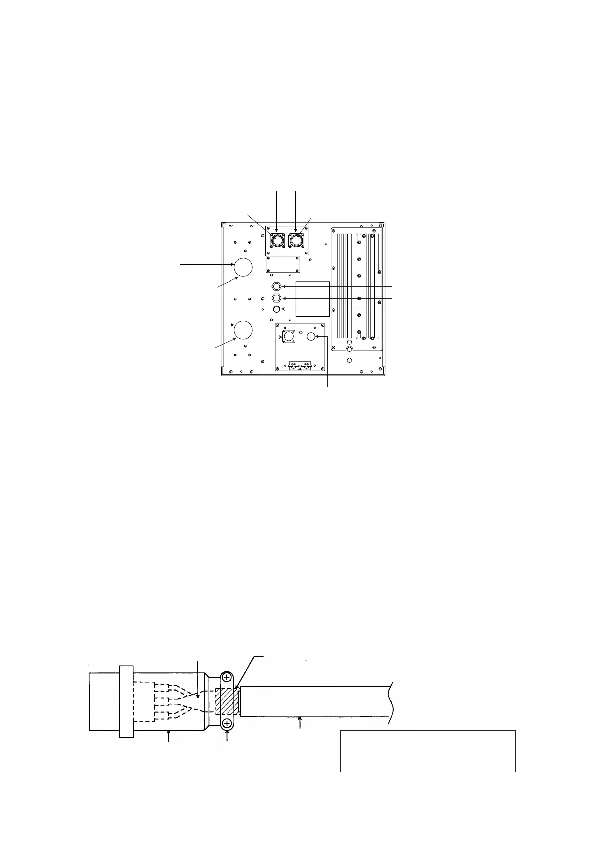
TRANSDUCER Connector*1
(4P)
NMEA Connector
TEMP Connector
SONDE Connector
POWER
Connector
Fuse (15A)
Earth Terminal
HIGH
LOW
*1: FCV-1500 only, FCV-1500M is covered.
*2: FCV-1500M only, FCV-1500 is covered.
External Interface connector*2 (24P)
HIGH
LOW
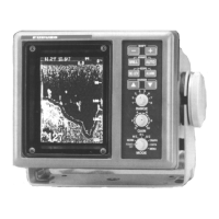
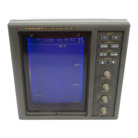
Figure 2-1 Display unit, rear view
2.1 General Wiring
Transducer (FCV-1500 only)
Separate the transducer cable as far apart as possible from other cables to prevent inter-
ference to this equipment. Fabricate the transducer cable as below and connect it to the
appropriate TRANSDUCER connector on the rear panel.
Shield
Connector
Cable Clamp
Cable
Clamp at shield.
2
4
3
Note: For the dual frequency transducer
connection, use the NCS255AD-L-500
cable assy (option).
Figure 2-2 How to attach connector to transducer cable
 Loading...