1. INITIAL SETTING AND ADJUSTMENT
1-49
10. Click the [Save] button. According to the data that you entered, the information of
the sensor information box is updated.
Note: For the heading data, use the data input from the heading sensor.
11. Monitor the route that the vessel is in the channel limit.
12. According to the autopilot connected with the ECDIS, do the following procedure.
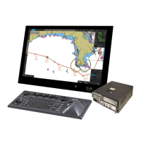
For FAP-3000, PR-6000 or PR-9000
Click the [TCS], [TCS Setting] button and se-
lect [Go AW] or [Go SEA] on the InstantAc-
cess bar
™
.
For PT-900 or NP-5400
Click the [TCS], [OP] button and select [Go
AW] or [Go SEA] on the InstantAccess
bar
™
.
For FAP-2000 or PT-500A
At the autopilot, push the Go AW or Go SEA button as appropriate.
13. Change the steering mode of the autopilot to NAV mode.
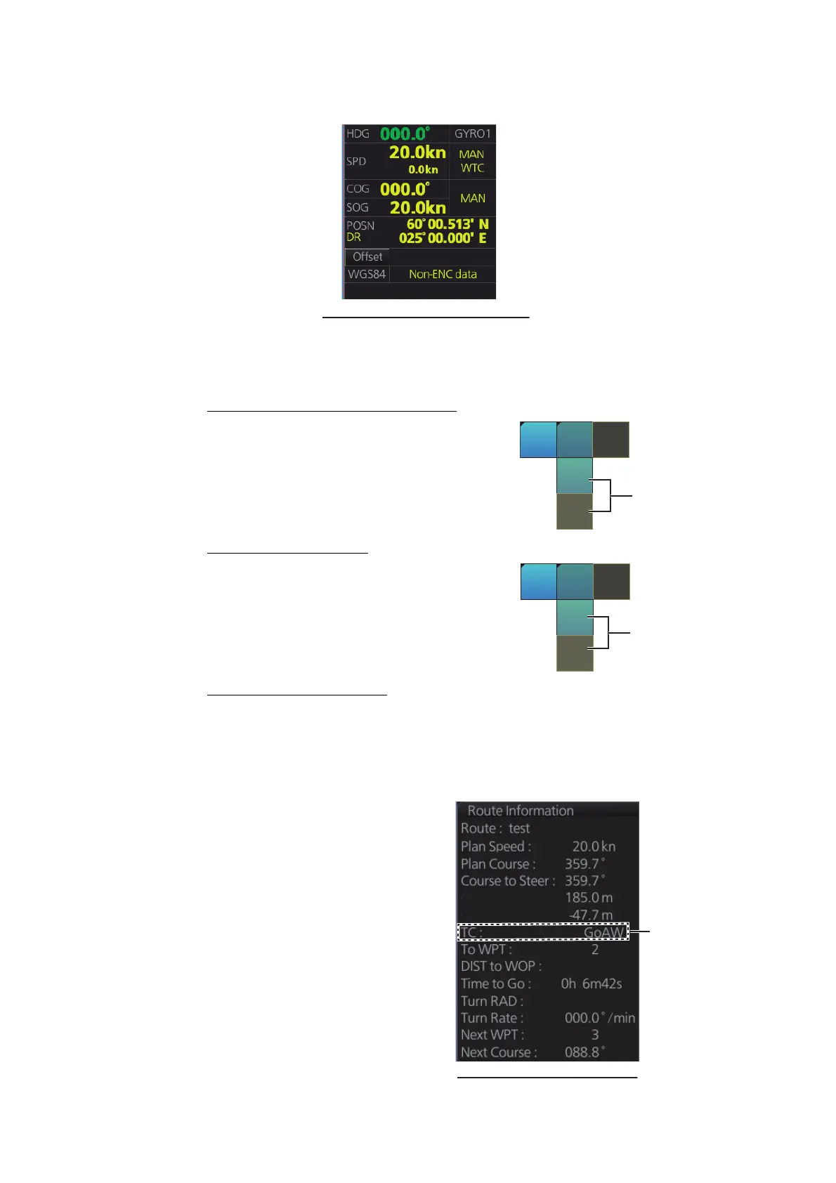
14. Confirm that [Go AW] or [Go SEA] appears at the [TC] column of the route infor-
mation box.
• [Go AW] or [Go SEA] appears:
The connection between the
ECDIS and autopilot is correct.
• [Go AW] or [Go SEA] does not
appear: Check the configuration
and connection between the
ECDIS and autopilot.
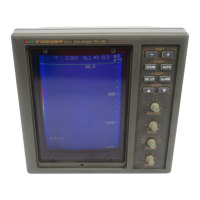
Example: Sensor information box
TCS
TCS
Setting
TCS
State
Go
AW
Go
SEA
Select [Go AW] or
[Go SEA].
Select [Go AW] or
[Go SEA].
TCS OP
TCS
Status
Go
AW
Go
SEA
Select [Go AW] or
[Go SEA].
Select [Go AW] or
[Go SEA].
Confirm that [Go
AW] or [Go SEA]
appears.
Confirm that [Go
AW] or [Go SEA]
appears.
Example: Route information box
2.20 NM
1.00 NM
XTD Limit:
XTD:
 Loading...