190-02692-00 Rev. A
Garmin G1000 Pilot’s Guide for the Piper PA-32 Saratoga
89
ENGINE INDICATION SYSTEM
SYSTEM
OVERVIEW
FLIGHT
INSTRUMENTS
EIS
AUDIO PANEL
& CNS
FLIGHT
MANAGEMENT
HAZARD
AVOIDANCE
AFCS
ADDITIONAL
FEATURES
APPENDICES INDEX
SECTION 3 ENGINE INDICATION SYSTEM
NOTE: The gauge values shown in this section are taken from an example configuration. Refer to the
current version of the pertinent flight manual for specific values and operating limitations.
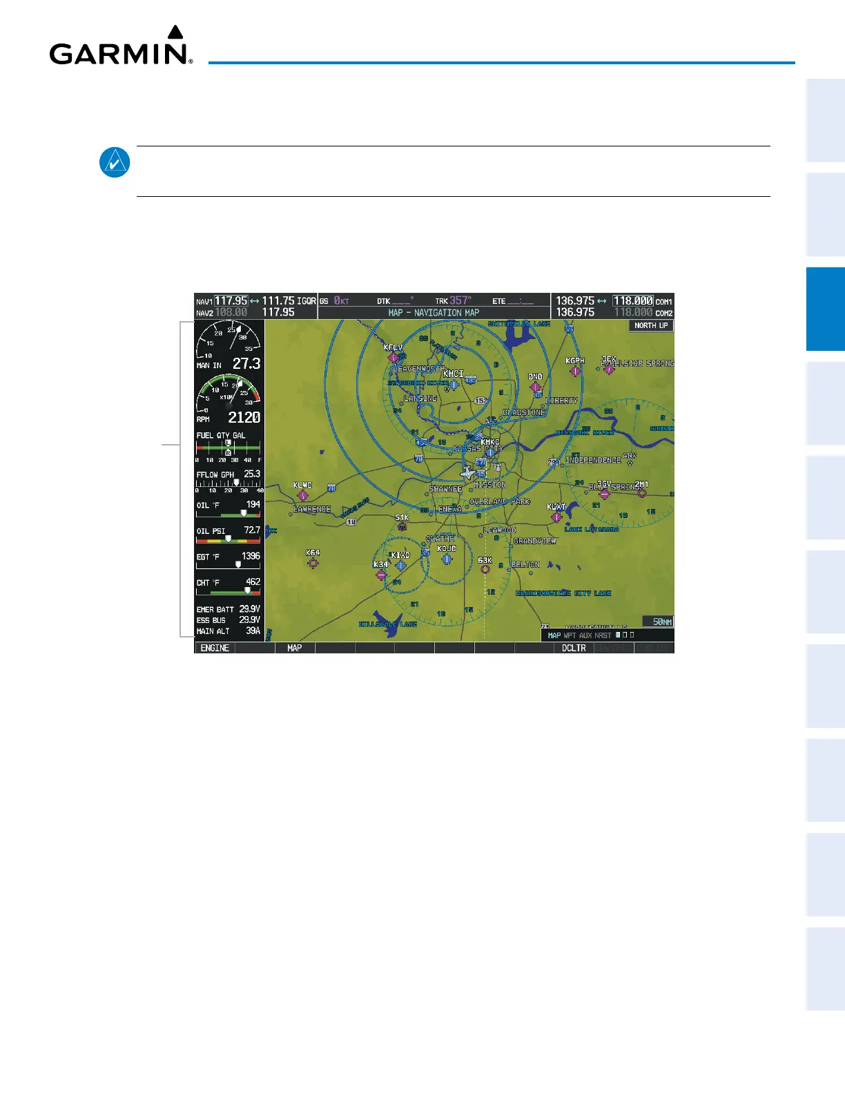
The system offers improved flight operations and reduces crew workload by automatically monitoring critical
system parameters and providing system alerts during all phases of flight. The Engine Indication System (EIS)
displays electrical, fuel, and engine information on the left side of the Multi Function Display (MFD). The EIS -
ENGINE page can be viewed by pressing the ENGINE Softkey.
Figure 3-1 MFD (Normally Aspirated)
EIS
Display
Green bands on the instruments indicate normal ranges of operation; amber and red bands indicate caution
and warning, respectively. White or uncolored bands indicate areas outside of normal operation not yet in the
caution or warning ranges. When unsafe operating conditions occur, the corresponding displays flash to indicate
cautions and warnings. If sensory data to an instrument becomes invalid or unavailable, a red“X” is displayed
across the instrument.

 Loading...


