190-01639-00 GSU 75 ADAHRS Installation Manual
Rev. 6 Page 4-6
4.3.2 GSU 75 Configuration Module
U
se of a configuration module is optional to retain configuration settings outside of the GSU 75.
4.3.3 RS-232 Serial Input/Output
The RS-232 outputs conform to EIA/TIA-232C with an output voltage swing of at least ±5 V when driving
a standard RS-232 load.
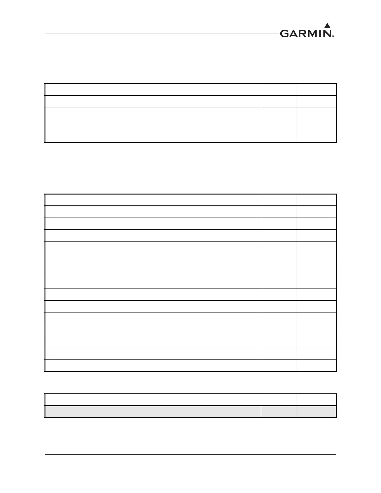
Table 4-7 GSU 75 Configuration Module
Pin Name Pin I/O
CONFIG MODULE POWER OUT 53 Out
CONFIG MODULE DATA 54 I/O
CONFIG MODULE CLOCK 55 Out
CONFIG MODULE GROUND 74 --
Table 4-8 GSU 75 RS-232 I/O
Pin Name Pin I/O
RS-232 IN ADC 1 70 In
RS-232 OUT ADC 1 69 Out
RS-232 ADC 1 GROUND 68 --
RS-232 IN ADC 2 18 In
RS-232 OUT ADC 2 17 Out
RS-232 ADC 2 GROUND 37 --
RS-232 IN AHRS 1 52 In
RS-232 OUT AHRS 1 51 Out
RS-232 AHRS 1 GROUND 32 --
RS-232 IN AHRS 2 72 In
RS-232 OUT AHRS 2 71 Out
RS-232 AHRS 2 GROUND 73 --
RS-232 OUT AHRS 3 12 Out
RS-232 AHRS 3 GROUND 31 --
Table 4-9 GMU 44 RS-232 I/O
Pin Name Pin I/O
RS-232 IN 8 In
The document reference is online, please check the correspondence between the online documentation and the printed version.
 Loading...