2.2 Flow path
Introduction
This section gives a generalized overview of the flow path in the ÄKTA pilot 600 instrument.
The flow path in a specific instrument is determined by the modules that are installed
and by the current settings in UNICORN software. Several functions such as the mixer,
air trap and columns can be switched in or out of the flow path as required by setting
to In-line or By-pass in the software.
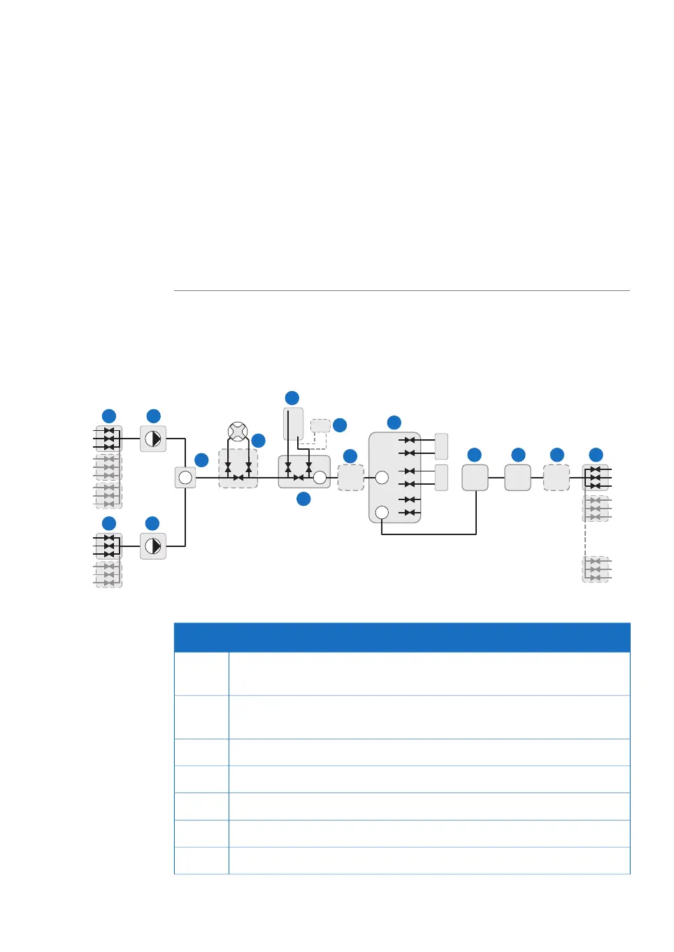
Flow diagram
The following illustration shows a schematic diagram of the flow path. Optional compo-
nents are marked with dashed outlines.
B1
B2
B3
A1
A2
A3
A5
A4
A6
A8
A7
A9
B5
B4
B6
1/W
2
3
P CondCond UV pH
P
AP
R
B
A
1
IP
W2
2
4
5
6
13
14
15
1
2
3
4
5
6
8
9
7
11
10
12 13 14 15
FunctionPart
Inlet valve A with 3 ports. Can be expanded to 9 ports with optional inlet
valves.
1
Inlet valve B with 3 ports. Can be expanded to 6 ports with optional inlet
valves.
2
System pump A3
System pump B4
Flow restrictor and system pressure sensor5
Mixer and mixer valve (optional)6
Air trap7
ÄKTA pilot 600 User Manual 29274559 AA 19
2 System description
2.2 Flow path

 Loading...