3.3.3 Inlets and outlets
Introduction
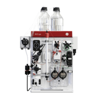
This section describes the inlets and outlets, including the drain outlet, of ÄKTAprocess
that are provided in the standard configuration.
Connections
The standard configuration of ÄKTAprocess has two inlets, two outlets and connections
for one column. As shown in the flowchart in Section 3.5 Flowchart, on page 72
ÄKTAprocess has a moveable air sensor that may be connected to any inlet.
For standard ÄKTAprocess configurations the pressure on the inlets should be in the
range 0 to 0.2 bar. The outlets can handle backpressure up to 1 bar.
Drains
All drains from ÄKTAprocess are collected to a single drain outlet. The drains are first
collected in an open cup to ensure that no back pressure is applied on any parts of the
processing system.
ÄKTAprocess Operating Instructions 29-0252-49 AA 57
3 System description
3.3 Standard components
3.3.3 Inlets and outlets
 Loading...