GE Multilin D60 Line Distance Protection System 5-231
5 SETTINGS 5.6 GROUPED ELEMENTS
5
• NEG SEQ DIR OC1 FWD PICKUP: This setting defines the pickup level for the overcurrent unit in the forward direc-
tion. Upon NEG SEQ DIR OC1 TYPE selection, this pickup threshold applies to zero- or negative-sequence current. When
selecting this setting it must be kept in mind that the design uses a positive-sequence restraint technique.
• NEG SEQ DIR OC1 REV LIMIT ANGLE: This setting defines a symmetrical (in both directions from the ECA) limit
angle for the reverse direction.
• NEG SEQ DIR OC1 REV PICKUP: This setting defines the pickup level for the overcurrent unit in the reverse direc-
tion. Upon
NEG SEQ DIR OC1 TYPE selection, this pickup threshold applies to zero- or negative-sequence current. When
selecting this setting it must be kept in mind that the design uses a positive-sequence restraint technique.
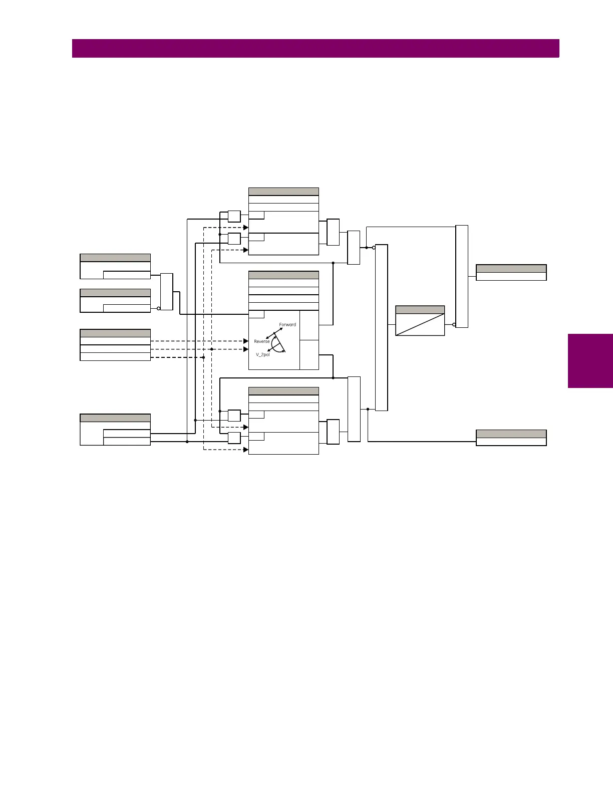
Figure 5–112: NEGATIVE SEQUENCE DIRECTIONAL OC1 SCHEME LOGIC
827091A7.CDR
AND
AND
AND
AND
AND
OR
OR
NOTE:
V_2 is negative-sequence voltage
I_2 is negative-sequence current
I_0 is zero-sequence current
AND
SETTING
Off = 0
Block
SETTING
= Neg Sequence
= Zero Sequence
Type
SETTINGS
Forward Pickup
RUN
( |3I_0| – × |I_1| ) PickupK ≥
Positive-Sequence Restraint
TIMER
1.25 cycles
1.5 cycles
FLEXLOGIC OPERAND
NEG SEQ DIR OC1 FWD
SETTING
Enabled = 1
Function
ACTUAL VALUES
V_2
I_2
I_0
RUN
( |I_2| – × |I_1| ) PickupK ≥
Voltage Polarization
SETTINGS
Forward ECA
RUN
Forward Limit Angle
Reverse Limit Angle
Offset
Forward
Reverse
SETTINGS
Reverse Pickup
RUN
( |I_2| – × |I_1| ) PickupK ≥
Pos Seq Restraint
RUN
( |3I_0| – × |I_1| ) PickupK ≥
AND
AND
AND
FLEXLOGIC OPERAND
NEG SEQ DIR OC1 REV

 Loading...


