GE Multilin D60 Line Distance Protection System 3-11
3 HARDWARE 3.2 WIRING
3
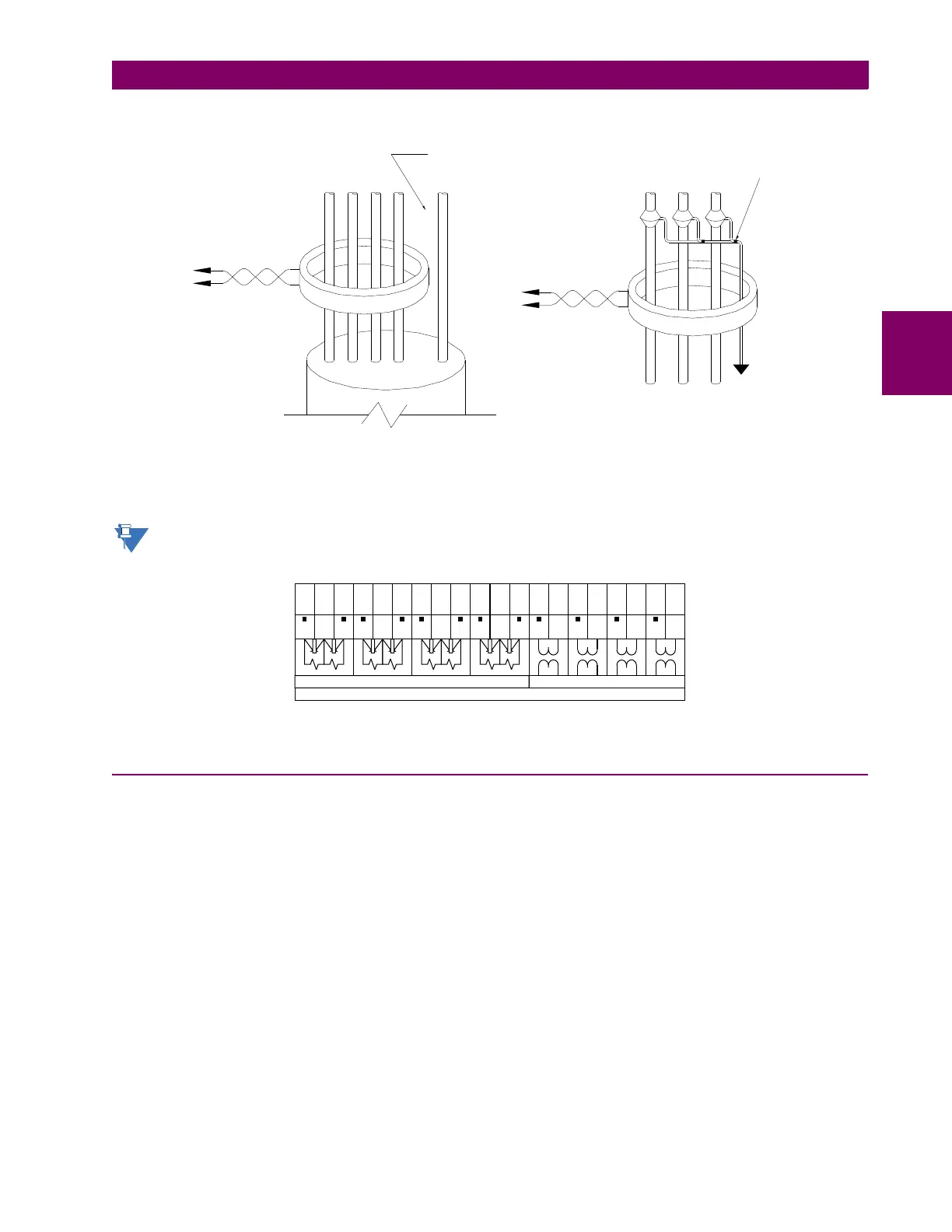
Figure 3–12: ZERO-SEQUENCE CORE BALANCE CT INSTALLATION
The phase voltage channels are used for most metering and protection purposes. The auxiliary voltage channel is used as
input for the synchrocheck and volts-per-hertz features.
Substitute the tilde “~” symbol with the slot position of the module in the following figure.
Figure 3–13: CT/VT MODULE WIRING
3.2.5 PROCESS BUS MODULES
The D60 can be ordered with a process bus interface module. This module is designed to interface with the GE Multilin
HardFiber system, allowing bidirectional IEC 61850 fiber optic communications with up to eight HardFiber merging units,
known as Bricks. The HardFiber system has been designed to integrate seamlessly with the existing UR-series applica-
tions, including protection functions, FlexLogic, metering, and communications.
The IEC 61850 process bus system offers the following benefits:
• Reduces labor associated with design, installation, and testing of protection and control applications using the D60 by
reducing the number of individual copper terminations
• Integrates seamlessly with existing D60 applications, since the IEC 61850 process bus interface module replaces the
traditional CT/VT modules
• Communicates using open standard IEC 61850 messaging
For additional details on the HardFiber system, see GE publication GEK-113658: HardFiber Process Bus System Instruc-
tion Manual.
Ground connection to neutral
must be on the source side
UNSHIELDED CABLE
LOAD
ABCN G
Ground
outside CT
Source
LOAD
SHIELDED CABLE
996630A6.CDR
ABC
Source
To ground;
must be on
load side
Stress cone
shields
~1a
~1b
~1c
~2a
~2b
~2c
~3a
~4a
~5a
~6a
~7a
~8a
~3b
~4b
~5c
~6c
~7c
~8c
~3c
~4c
Current inputs
8F, 8G, 8L, and 8M modules (4 CTs and 4 VTs)
Voltage inputs
VA
VB
VC
VX
VA
VB
VC
VX
IA
IC
IB
IG
IA5
IC5
IB5
IG5
IA1
IC1
IB1
IG1
842768A2.CDR

 Loading...


