B-6 D60 Line Distance Protection System GE Multilin
B.2 MODBUS FUNCTION CODES APPENDIX B
B
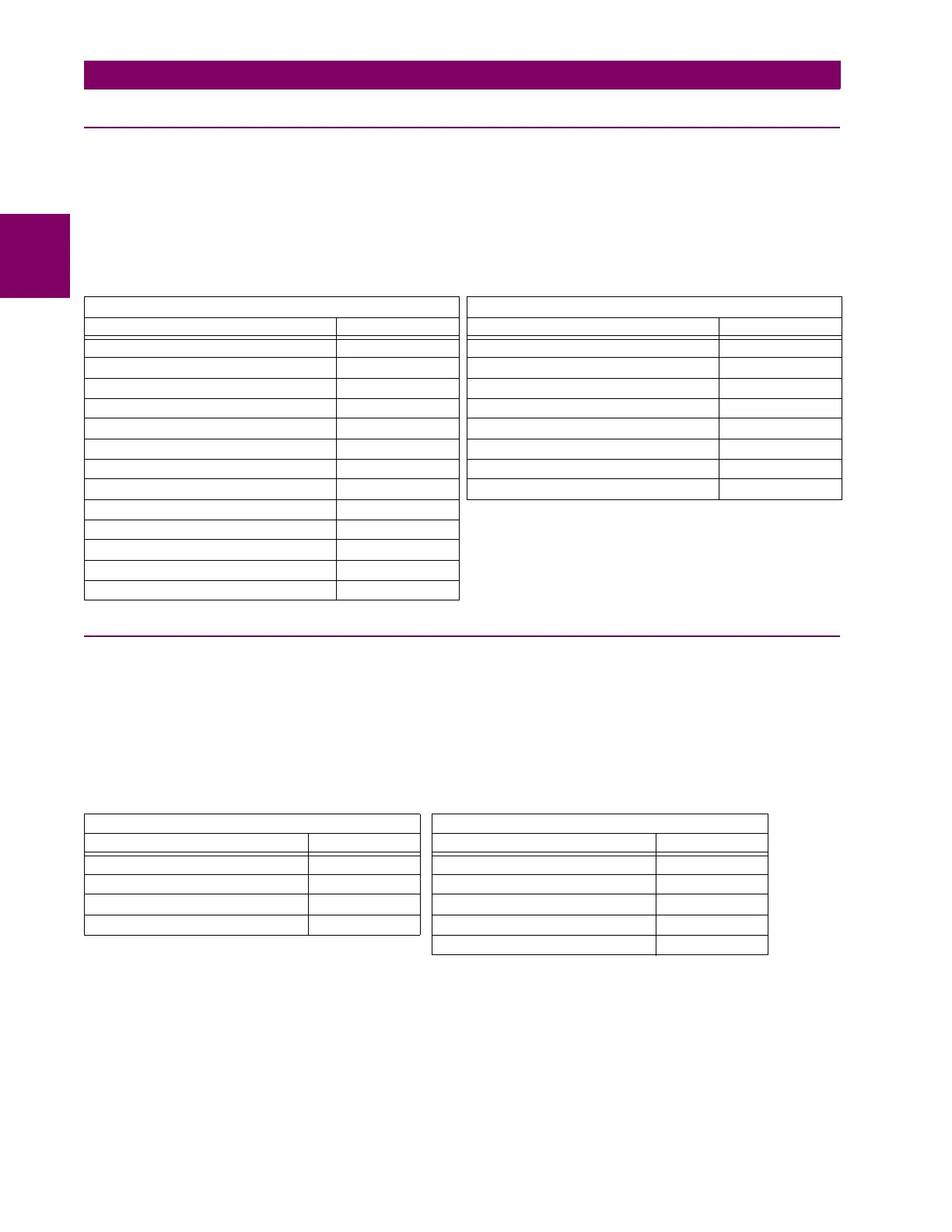
B.2.5 STORE MULTIPLE SETTINGS (FUNCTION CODE 10H)
This function code allows the master to modify the contents of a one or more consecutive setting registers in a relay. Setting
registers are 16-bit (two byte) values transmitted high order byte first. The maximum number of setting registers that can be
stored in a single packet is 60. The following table shows the format of the master and slave packets in Modbus RTU. Mod-
bus TCP/IP ADUs have a MBAP instead of slave address, and CRC is in another stack layer. The example shows a master
device storing the value 200 at memory map address 4051h, and the value 1 at memory map address 4052h to slave
device 11h (17 decimal).
B.2.6 EXCEPTION RESPONSES
Programming or operation errors usually happen because of illegal data in a packet. These errors result in an exception
response from the slave. The slave detecting one of these errors sends a response packet to the master with the high order
bit of the function code set to 1.
The following table shows the format of the master and slave packets in Modbus RTU. Modbus TCP/IP ADUs have a
MBAP instead of slave address, and CRC is in another stack layer. The example shows a master device sending the
unsupported function code 39h to slave device 11h.
Table B–8: MASTER AND SLAVE DEVICE PACKET TRANSMISSION EXAMPLE
MASTER TRANSMISSION SLAVE RESPONSE
PACKET FORMAT EXAMPLE (HEX) PACKET FORMAT EXAMPLE (HEX)
SLAVE ADDRESS 11 SLAVE ADDRESS 11
FUNCTION CODE 10 FUNCTION CODE 10
DATA STARTING ADDRESS - hi 40 DATA STARTING ADDRESS - hi 40
DATA STARTING ADDRESS - lo 51 DATA STARTING ADDRESS - lo 51
NUMBER OF SETTINGS - hi 00 NUMBER OF SETTINGS - hi 00
NUMBER OF SETTINGS - lo 02 NUMBER OF SETTINGS - lo 02
BYTE COUNT 04 CRC - lo 07
DATA #1 - high order byte 00 CRC - hi 64
DATA #1 - low order byte C8
DATA #2 - high order byte 00
DATA #2 - low order byte 01
CRC - low order byte 12
CRC - high order byte 62
Table B–9: MASTER AND SLAVE DEVICE PACKET TRANSMISSION EXAMPLE
MASTER TRANSMISSION SLAVE RESPONSE
PACKET FORMAT EXAMPLE (HEX) PACKET FORMAT EXAMPLE (HEX)
SLAVE ADDRESS 11 SLAVE ADDRESS 11
FUNCTION CODE 39 FUNCTION CODE B9
CRC - low order byte CD ERROR CODE 01
CRC - high order byte F2 CRC - low order byte 93
CRC - high order byte 95

 Loading...


