5-244 D60 Line Distance Protection System GE Multilin
5.6 GROUPED ELEMENTS 5 SETTINGS
5
c) PHASE OVERVOLTAGE (ANSI 59P, IEC PTOV)
PATH: SETTINGS GROUPED ELEMENTS SETTING GROUP 1(6) VOLTAGE ELEMENTS PHASE OVERVOLTAGE1(3)
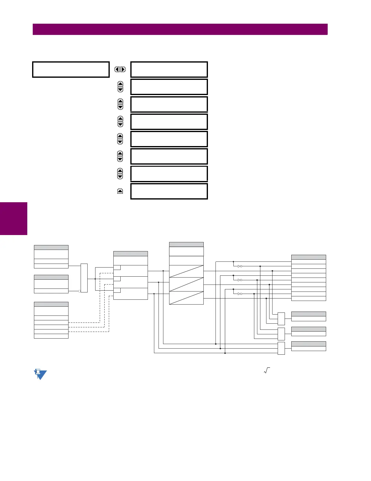
There are three phase overvoltage elements available. A phase overvoltage element is used as an instantaneous element
with no intentional time delay or as a definite time element. The input voltage is the phase-to-phase voltage, either mea-
sured directly from delta-connected VTs or as calculated from phase-to-ground (wye) connected VTs. The specific voltages
to be used for each phase are shown below.
Figure 5–121: PHASE OVERVOLTAGE SCHEME LOGIC
If the source VT is wye-connected, then the phase overvoltage pickup condition is for V
AB
, V
BC
,
and V
CA
.
PHASE
OVERVOLTAGE1
PHASE OV1
FUNCTION: Disabled
Range: Disabled, Enabled
MESSAGE
PHASE OV1 SIGNAL
SOURCE: SRC 1
Range: SRC 1, SRC 2, SRC 3, SRC 4
MESSAGE
PHASE OV1
PICKUP: 1.000 pu
Range: 0.000 to 3.000 pu in steps of 0.001
MESSAGE
PHASE OV1 PICKUP
DELAY: 1.00 s
Range: 0.00 to 600.00 s in steps of 0.01
MESSAGE
PHASE OV1 RESET
DELAY: 1.00 s
Range: 0.00 to 600.00 s in steps of 0.01
MESSAGE
PHASE OV1 BLOCK:
Off
Range: FlexLogic Operand
MESSAGE
PHASE OV1
TARGET: Self-reset
Range: Self-reset, Latched, Disabled
MESSAGE
PHASE OV1
EVENTS: Disabled
Range: Disabled, Enabled
PHASE OV1
SOURCE:
Source VT = Delta
Source VT = Wye
VAB
VBC
VCA
PHASE OV1 A PKP
PHASE OV1 B PKP
PHASE OV1 C PKP
PHASE OV1 OP
PHASE OV1 A DPO
PHASE OV1 B DPO
PHASE OV1 C DPO
PHASE OV1 A OP
PHASE OV1 B OP
PHASE OV1 C OP
PHASE OV1 DPO
AND
PHASE OV1
FUNCTION:
Disabled = 0
Enabled = 1
SETTING
PHASE OV1
BLOCK:
Off=0
SETTING
SETTING
PHASE OV1
PICKUP:
SETTING
FLEXLOGIC OPERANDS
FLEXLOGIC OPERAND
FLEXLOGIC OPERAND
827066A7.CDR
RUN
VAB PICKUP≥
RUN
VBC PICKUP≥
RUN
VCA PICKUP≥
AND
OR
PHASE OV1 PKP
FLEXLOGIC OPERAND
OR
PHASE OV1 RESET
DELAY:
SETTINGS
t
PKP
t
PKP
t
PKP
t
RST
t
RST
t
RST
PHASE OV1 PICKUP
DELAY:

 Loading...


