5-254 D60 Line Distance Protection System GE Multilin
5.6 GROUPED ELEMENTS 5 SETTINGS
5
• DIR POWER 1 RCA: Specifies the relay characteristic angle (RCA) for the sensitive directional power function. Appli-
cation of this setting is threefold:
1. It allows the element to respond to active or reactive power in any direction (active overpower/underpower, etc.).
2. Together with a precise calibration angle, it allows compensation for any CT and VT angular errors to permit more
sensitive settings.
3. It allows for required direction in situations when the voltage signal is taken from behind a delta-wye connected
power transformer and the phase angle compensation is required.
For example, the active overpower characteristic is achieved by setting DIR POWER 1 RCA to “0°”, reactive overpower by
setting DIR POWER 1 RCA to “90°”, active underpower by setting DIR POWER 1 RCA to “180°”, and reactive underpower by
setting DIR POWER 1 RCA to “270°”.
• DIR POWER 1 CALIBRATION: This setting allows the relay characteristic angle to change in steps of 0.05°. This may
be useful when a small difference in VT and CT angular errors is to be compensated to permit more sensitive settings.
This setting virtually enables calibration of the directional power function in terms of the angular error of applied VTs
and CTs. The element responds to the sum of the
DIR POWER 1 RCA and DIR POWER 1 CALIBRATION settings.
• DIR POWER 1 STG1 SMIN: This setting specifies the minimum power as defined along the relay characteristic angle
(RCA) for the stage 1 of the element. The positive values imply a shift towards the operate region along the RCA line;
the negative values imply a shift towards the restrain region along the RCA line. Refer to the Directional power sample
applications figure for details. Together with the RCA, this setting enables a wide range of operating characteristics.
This setting applies to three-phase power and is entered in per-unit (pu) values. The base quantity is 3 x VT pu base x
CT pu base.
For example, a setting of 2% for a 200 MW machine is 0.02 200 MW = 4 MW. If 13.8kV is line voltage and 10 kA is a
primary CT current, the source pu quantity is 239 MVA, and thus, SMIN should be set at 4 MW / 239 MVA = 0.0167 pu
0.017 pu. If the reverse power application is considered, RCA = 180° and SMIN = 0.017 pu.
The element drops out if the magnitude of the positive-sequence current becomes virtually zero, that is, it drops below
the cutoff level.
• DIR POWER 1 STG1 DELAY: This setting specifies a time delay for stage 1. For reverse power or low forward power
applications for a synchronous machine, stage 1 is typically applied for alarming and stage 2 for tripping.
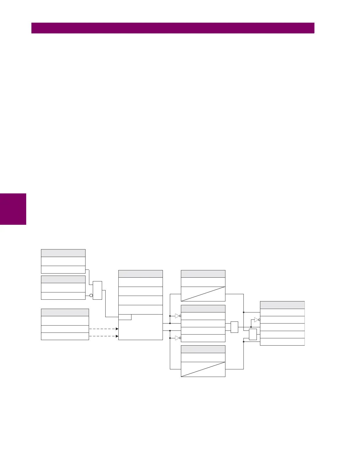
Figure 5–131: SENSITIVE DIRECTIONAL POWER SCHEME LOGIC
842003A3.CDR
DIR POWER 1 BLK:
SETTING
Off = 0
DIRECTIONAL POWER
CHARACTERISTICS
RUN
FLEXLOGIC OPERANDS
DIR POWER 1 SOURCE:
SETTING
Three-phase active power (P)
Three-phase reactive power (Q)
DIR POWER 1 STG1
SMIN:
DIR POWER 1
CALIBRATION:
SETTING
DIR POWER 1 STG1
DELAY:
t
PKP
100 ms
DIR POWER 1
FUNCTION:
SETTING
Enabled = 1
SETTING
DIR POWER 1 STG2
DELAY:
DIR POWER 1 STG1 OP
DIR POWER 1 STG2 PKP
DIR POWER 1 STG2 DPO
DIR POWER 1 STG2 OP
DIR POWER 1 PKP
DIR POWER 1 DPO
DIR POWER 1 OP
FLEXLOGIC™ OPERANDS
DIR POWER 1 STG1 PKP
DIR POWER 1 STG1 DPO
100 ms
OR
SETTINGS
DIR POWER 1 RCA:
OR
t
PKP
DIR POWER 1 STG2
SMIN:
AND

 Loading...


