5-258 D60 Line Distance Protection System GE Multilin
5.7 CONTROL ELEMENTS 5 SETTINGS
5
The 61850 standard provides for the ability to monitor, edit, and change setting groups in a relay through a series of ser-
vices operating on Setting Group Control Block values. There is one SGCB in LLN0 in LD1 in the UR as, at present, the
other LDs do not support multiple setting groups The default value of SETTING GROUPS is Disabled. In order for 61850 and/
or UR setting group control to function, the
SETTING GROUPS FUNCTION must be set to Enabled.
The active setting group in the UR is settable from either the value set via a FlexLogic operand in the UR (present practice)
or a SelectActiveSG command from a 61850 Client. For both the UR and IEC 61850, the default active setting group is "1".
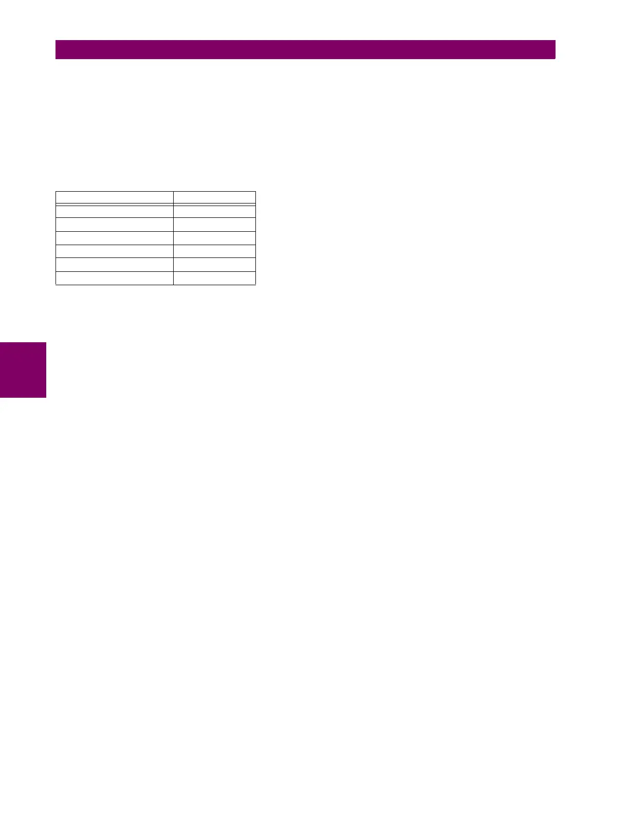
A 61850 SelectActiveSG command sets one of the internal Non-Volatile flags (61850 SG Level x) that represents the
requested Active Setting Group shown as follows:
On power-up or restart, the previously selected 61850 SG Level x is re-instated. Similarly, the input to the setting group
control in the UR can be designed with Non-Volatile latches to achieve the same effect.
The setting groups menu controls the activation and deactivation of up to six possible groups of settings in the
GROUPED
ELEMENTS settings menu. The faceplate Settings In Use LEDs indicate which active group (with a non-flashing energized
LED) is in service.
The SETTING GROUPS BLK setting prevents the active setting group from changing when the FlexLogic parameter is set to
"On". This can be useful in applications where it is undesirable to change the settings under certain conditions, such as the
breaker being open.
The
GROUP 2 ACTIVATE ON to GROUP 6 ACTIVATE ON settings select a FlexLogic operand which, when set, makes the partic-
ular setting group active for use by any grouped element. A priority scheme ensures that only one group is active at a given
time – the highest-numbered group that is activated by its ACTIVATE ON parameter takes priority over the lower-numbered
groups. There is no activate on setting for group 1 (the default active group), because group 1 automatically becomes
active if no other group is active.
The
SETTING GROUP 1 NAME to SETTING GROUP 6 NAME settings allows the user to assign a name to each of the six settings
groups. Once programmed, this name appears on the second line of the GROUPED ELEMENTS SETTING GROUP 1(6) menu
display.
The relay can be set up via a FlexLogic equation to receive requests to activate or de-activate a particular non-default set-
tings group. The following FlexLogic equation (see the following figure) illustrates requests via remote communications (for
example,
VIRTUAL INPUT 1 ON) or from a local contact input (for example, CONTACT IP 1 ON) to initiate the use of a particu-
lar settings group, and requests from several overcurrent pickup measuring elements to inhibit the use of the particular set-
tings group. The assigned
VIRTUAL OUTPUT 1 operand is used to control the “On” state of a particular settings group.
Table 5–33: ACTIVE SETTING GROUP
SELECTACTIVESG VALUE FLAG SET
1 (default) SG Level 1
2 SG Level 2
3 SG Level 3
4 SG Level 4
5 SG Level 4
6 SG Level 6

 Loading...


