GE Multilin D60 Line Distance Protection System 5-347
5 SETTINGS 5.8 INPUTS AND OUTPUTS
5
The FlexLogic operand response time to the contact input change is equal to the debounce time setting plus up to one pro-
tection pass (variable and depending on system frequency if frequency tracking enabled). If the change of state occurs just
after a protection pass, the recognition is delayed until the subsequent protection pass; that is, by the entire duration of the
protection pass. If the change occurs just prior to a protection pass, the state is recognized immediately. Statistically a delay
of half the protection pass is expected. Owing to the 0.5 ms scan rate, the time resolution for the input contact is below
1msec.
For example, 8 protection passes per cycle on a 60 Hz system correspond to a protection pass every 2.1 ms. With a con-
tact debounce time setting of 3.0 ms, the FlexLogic operand-assert time limits are: 3.0 + 0.0 = 3.0 ms and 3.0 + 2.1 = 5.1
ms. These time limits depend on how soon the protection pass runs after the debouncing time.
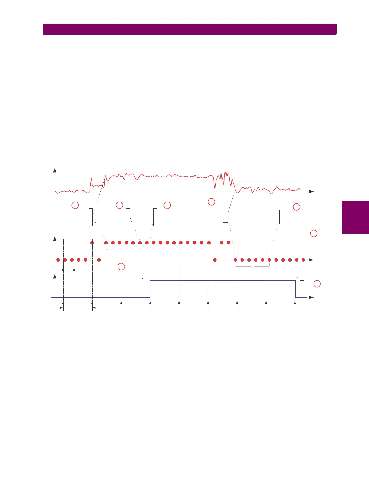
Regardless of the contact debounce time setting, the contact input event is time-stamped with a 1 s accuracy using the
time of the first scan corresponding to the new state (mark no. 2 below). Therefore, the time stamp reflects a change in the
DC voltage across the contact input terminals that was not accidental as it was subsequently validated using the debounce
timer. Keep in mind that the associated FlexLogic operand is asserted/de-asserted later, after validating the change.
The debounce algorithm is symmetrical: the same procedure and debounce time are used to filter the LOW-HIGH (marks
no.1, 2, 3, and 4 in the figure below) and HIGH-LOW (marks no. 5, 6, 7, and 8 below) transitions.
Figure 5–173: INPUT CONTACT DEBOUNCING MECHANISM AND TIME-STAMPING SAMPLE TIMING
Contact inputs are isolated in groups of four to allow connection of wet contacts from different voltage sources for each
group. The
CONTACT INPUT THRESHOLDS determine the minimum voltage required to detect a closed contact input. This
value should be selected according to the following criteria: 17 for 24 V sources, 33 for 48 V sources, 84 for 110 to 125 V
sources and 166 for 250 V sources.
For example, to use contact input H5a as a status input from the breaker 52b contact to seal-in the trip relay and record it in
the Event Records menu, make the following settings changes:
CONTACT INPUT H5A ID: "Breaker Closed (52b)"
CONTACT INPUT H5A EVENTS: "Enabled"
Note that the 52b contact is closed when the breaker is open and open when the breaker is closed.
842709A1.cdr
DEBOUNCE TIME
(user setting)
At thistime, the
new (HIGH)
contact state is
validated
The FlexLogic
TM
operand isgoing to
be asserted at this
protection pass
The FlexLogic
TM
operand
changes reflecting the
validated contact state
Time stamp of the first
scan corresponding to
the new validated state is
logged intheSOE record
2 1 3
4
DEBOUNCE TIME
(user setting)
At thistime, the new
(LOW) contact state is
validated
The FlexLogic
TM
operand isgoing to be
de-asserted at this
protection pass
The FlexLogic
TM
operand
changes reflecting the
validated contact state
5
7
8
Time stamp of the first
scan corresponding to the
new validated state is
logged intheSOE record
6
SCAN TIME
(0.5 msec)
PROTECTION PASS
(8 times a cycle controlled by the
frequency tracking mechanism )
RAW CONTACT
STATE
FLEXLOGIC
TM
OPERAND
INPUT
VOLTAGE
USER-PROGRAMMABLE THRESHOLD

 Loading...


