Chapter 4 Functional Checks Page: 89 Overview Provides procedures for checking major functions, diagnostics, and power supply adjustments.
Required Equipment Lists the necessary equipment, specifically transducers, for performing functional tests.
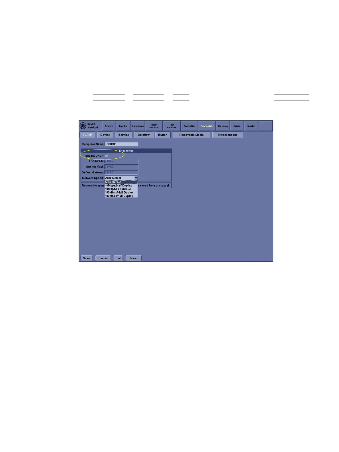
General Procedure Details the general steps for powering the system on and off, including boot-up and shutdown sequences.
System Features Provides an overview of the control panel and softMenu key functions for system operation.
B Mode Checks Covers preparations and operational panel controls for the B-Mode imaging function.
M Mode Controls Details the operational panel controls and softMenu key functions for M Mode imaging.
Color Flow Mode Checks Explains preparations and operational panel controls for the Color Flow Mode imaging function.
Doppler Mode Checks Covers preparations and operational panel controls for Doppler Mode imaging, including PW and spectral Doppler.
CWD Functional Check Details the procedure for activating and exiting the Continuous Wave Doppler (CWD) mode.
Basic Measurements Guides on performing distance, tissue depth, circumference, and area measurements.
Probe/Connectors Usage Provides instructions on connecting and disconnecting probes, including safety precautions.
Using Cine Explains how to activate CINE, move between frames, and adjust playback speed for recorded loops.
Peripheral Checks Describes how to check the functionality of peripherals like printers, footswitches, and ECG.
Chapter 5 Components and Functions (Theory) Page: 127 Overview Explains system concepts, component arrangement, subsystem function, PDS, and probes.
Power Diagrams Explains the AC power system, including its tasks, input range, and circuit breaker functionality.
Common Service Platform Introduces the service platform software modules common to ultrasound systems, improving service efficiency.
Error Logs Tab Describes the Log Viewer, its categories, color-coding for severity, and log entry details.
Diagnostics Covers diagnostic execution, reports, and user diagnostic pages, with detailed info in Chapter 7.
Chapter 9 Renewal Parts Page: 207 Overview Provides an overview of spare parts available for the LOGIQ e/LOGIQ e Vet/LOGIQ i/Vivid e systems.
List of Abbreviations Lists common abbreviations used in the manual, such as Assy, Ctrl, FRU, KBD, LCD, etc.
Renewal Parts Lists Details part replacements using 'Replaced By' column and lists equipment models covered in this chapter.
Operator Console Assy Illustrates the operator console assembly, identifying major components like LCD and Keyboard Assy.
LCD Assy Provides detailed diagrams and part numbers for the LCD assembly components.
Keyboard Assy Shows diagrams of the keyboard assembly and its various components, including trackball and key assemblies.
Bottom Assy Illustrates the components of the bottom assembly, including various boards, fans, and HDD.
Cables Illustrates the wiring diagram showing connections between major assemblies like LCD, KBD, and fans.
Accessories and Kits Lists various accessories and kits, including battery packs, DVD-RW drives, printers, and USB devices.
Manuals Lists available manuals and quick start guides for different LOGIQ and Vivid models and software versions.
Probe Lists probes compatible with LOGIQ e, Vivid e, and LOGIQ i systems, including their part numbers and frequencies.
Chapter 10 Care & Maintenance Page: 249 Overview Determines that no mandatory periodic maintenance inspections are required, but customer programs may differ.
Why do Maintenance Explains the importance of maintenance for safety, dependability, performance, and gaining accreditation.
Tools Required Lists special tools, supplies, and equipment needed for care and maintenance, including specific requirements.
System Maintenance Outlines preliminary checks, functional checks, peripheral/option checks, input power, and cleaning procedures.
Electrical Safety Tests Details electrical safety tests conforming to IEC 60601-1, focusing on leakage current and patient safety.