APPENDIX C
C-1
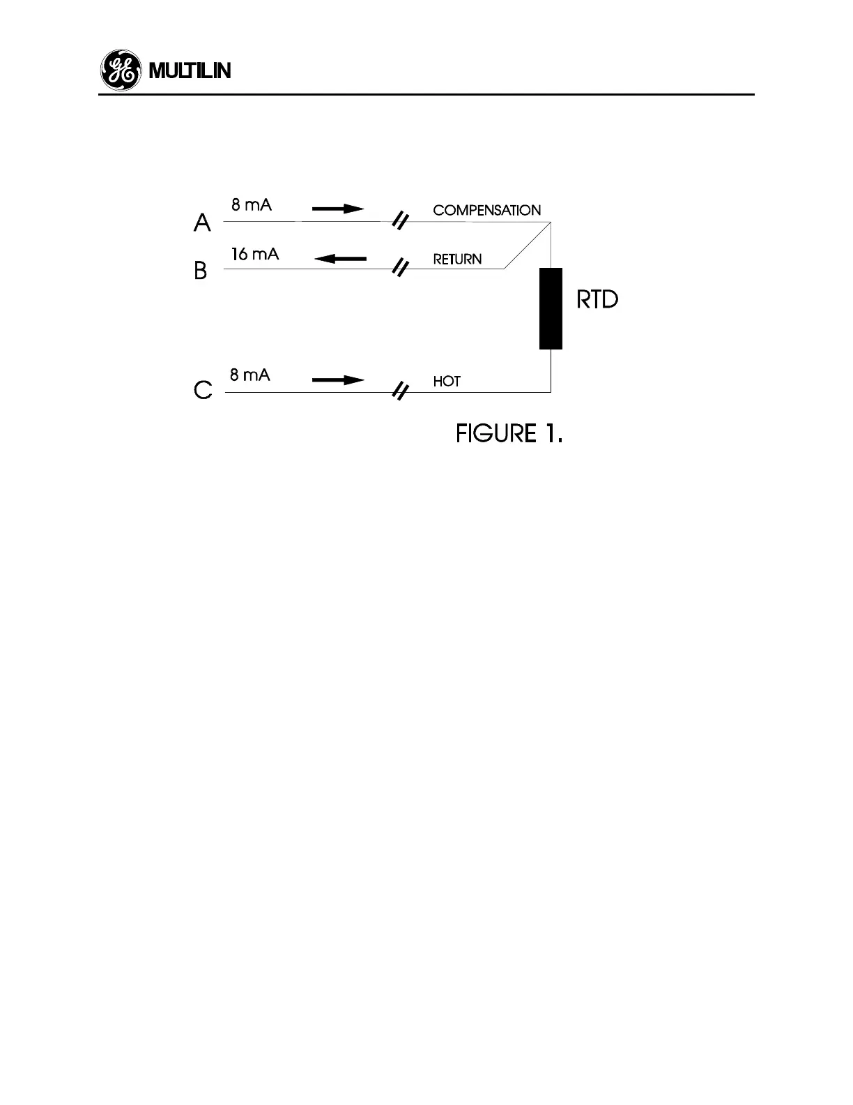
269 RTD Circuitry
The following is an explanation of how the RTD circuitry works in the 269 Motor Protection Relays.
A constant current source sends 8mA DC down legs A and C. 16mA DC returns down leg B. It may be seen that:
V
AB
= V
Lead A
+ V
Lead B
and
V
BC
= V
Lead C
+ V
RTD
+ V
Lead B
or
V
AB
= V
COMP
+ V
RETURN
and
V
BC
= V
HOT
+ V
RTD
+ V
RETURN
The above holds true providing that all three leads are the same length, gage, and material, hence the same resis-
tance.
⇒ R
Lead A
= R
Lead B
= R
Lead C
= R
Lead
or R
HOT
= R
COMP
= R
RETURN
= R
Lead
Electronically, subtracting V
AB
from V
BC
leaves only the voltage across the RTD. In this manner lead length is
effectively negated:
V
BC
- V
AB
= {V
Lead
+ V
RTD
+ V
Lead
} - {V
Lead
+ V
Lead
}
V
BC
- V
AB
= V
RTD
In order to connect 6 Stator RTDs with only 8 wires, the wiring illustrated in figure 2 may be used. However, this is
not a recommended wiring practice. All the HOT wires must travel to the 269 (6 wires). The compensation and
RETURN leads must be daisy-chained at the motor.
 Loading...


