1 INTRODUCTION
1-4
1.5 Technical Specifications
Phase Current Inputs
conversion: calibrated RMS, sample time 2ms
range: 0.05 to 12 × phase CT primary amps set-
point
full scale: 12 × phase CT primary amps setpoint
accuracy: ± 0.5% of full scale
(0.05 to 2 × phase CT primary amps set-
point)
± 1.0% of full scale
(over 2 × phase CT primary amps set-
point)
Frequency: 20–400 Hz
Ground Fault Current Input
conversion: calibrated RMS, sample time 2ms
range: 0.1 to 1.0 × G/F CT primary amps set-
point (5 Amp secondary CT)
1.0 to 10.0 amps 50:0.025A (2000:1 ratio)
full scale: 1 × G/F CT primary amps setpoint
(5 Amp secondary CT)
10 amps (2000:1 CT)
accuracy: ± 4% of G/F CT primary amps setpoint
(5 Amp secondary CT)
± 0.3 amps primary (2000:1 CT)
Frequency: 20–400 Hz
Overload Curves
curves: 8 curves fixed shape
trip time accuracy: ± 1 sec. up to 13 sec.
± 8% of trip time over 13 sec.
detection level: ± 1% of primary CT amps
Unbalance
display accuracy: ± 2 percentage points of true negative
sequence unbalance (In/Ip)
Running Hours Counter
accuracy: ± 1%
Relay Lock-out Time
accuracy: ± 1 minute with control power applied
± 20% of total lock-out time with no con-
trol power applied
Trip/Alarm Delay Times
accuracy: ± 0.5 sec. or 2% of total time, whichever
is greater with the exception of:
1. "INST."setpoints: 20–45ms
2. Ground Fault 0.5 Second delay: +/-
150 msec.
3. Ground Fault 250 msec delay: +75
msec, -150 msec.
4. Metering setpoints (Page 7): +/- 1.5sec
or 2% of total time
Differential Relay Input
relay response time: 100 msec. maximum (contact
closure to output relay activation)
RTD Inputs
sensor types: 10 OHM copper
100 OHM nickel
120 OHM nickel
100 OHM platinum
(specified with order)
display accuracy: ± 2 C
trip/alarm setpoint range: 0-200 °C
dead band: 3 C
maximum lead resistance:25% of RTD 0 °C resistance
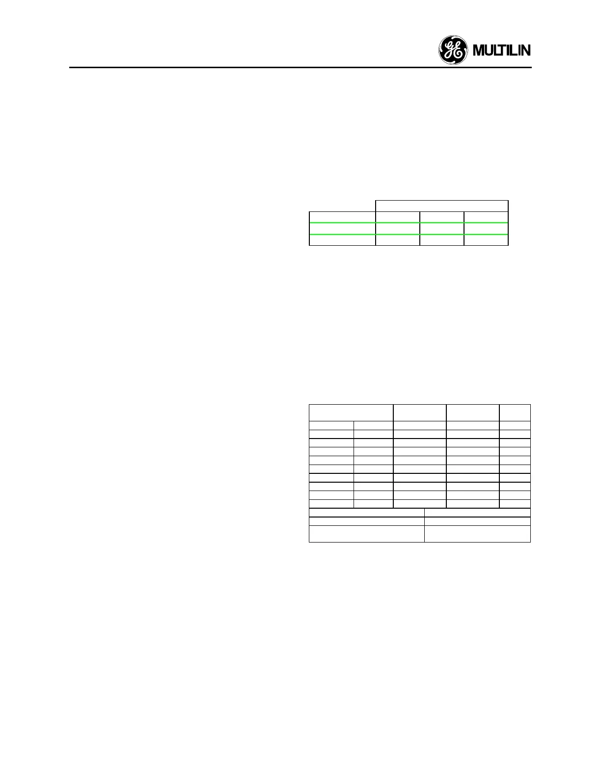
Analog Current Output (4-20 mA standard)
PROGRAMMABLE
OUTPUT 0-1 mA 0-20 mA 4-20 mA
MAX LOAD
2000 Ω 300 Ω 300 Ω
MAX OUTPUT 1.01 mA 20.2 mA 20.2 mA
accuracy: ± 1% of full scale reading
polarity: terminal 58 ("-") must be at
ground potential (i.e. output is
not isolated)
Isolation: non-isolated, active source
Update Time: 250 ms max.
Communications
Type: RS485 2-wire, half duplex, isolated
Baud Rate: 300, 1200, 2400
Protocol: Subset of Modbus
®
RTU
Functions: Read/write setpoints (03/16),
Read actual values (03/04)
Relay Contacts
VOLTAGE
MAKE/CARRY
CONTINUOUS
MAKE/CARRY
0.2 sec
BREAK
30 VDC 10 30 10
RESISTIVE 125 VDC 10 30 0.5
250 VDC 10 30 0.3
30 VDC 10 30 5
INDUCTIVE 125 VDC 10 30 0.25
(L/R=7ms) 250 VDC 10 30 0.15
RESISTIVE 120 VAC 10 30 10
250 VAC 10 30 10
INDUCTIVE 120 VAC 10 30 4
PF=0.4 250 VAC 10 30 3
CONFIGURATION FORM C NO/NC
CONTACT MATERIAL SILVER ALLOY
MINIMUM PERMISSIBLE LOAD 5 VDC, 100 mA
12 VAC, 100 mA
Switch Inputs
Type: dry contacts
 Loading...


