Actual Values, Pg. 1 3 SETUP AND USE
3-7
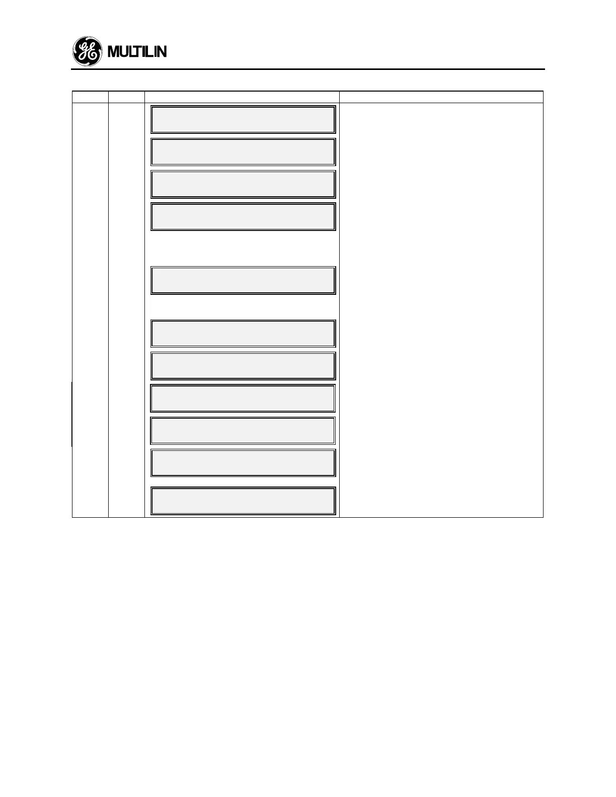
Table 3-2 ACTUAL VALUES
Page Line Information Line Description
1 1
PAGE 1: ACTUAL VALUESPAGE 1: ACTUAL VALUES
PHASE CURRENT DATAPHASE CURRENT DATA
ACTUAL VALUES page 1 header.
2
MOTOR STARTINGMOTOR STARTING
###1###2###3###4###5###6###1###2###3###4###5###6
Motor starting current level (seen only during a
motor start).
3 *
I1= XXXX I2= XXXXI1= XXXX I2= XXXX
I3= XXXX (AMPS) ---I3= XXXX (AMPS) ---
Motor phase current data.
("---" becomes "RUN" when motor is running.)
4
I(3 ph avg) = XXXX AMPSI(3 ph avg) = XXXX AMPS
Max Stator RTD = XXX CMax Stator RTD = XXX C
Average of 3 phase currents. Maximum of 6
stator RTDs. This line is shown only if the an-
swer to the question “ARE THERE ANY RTDs
CONNECTED?” is “YES”. This setpoint is lo-
cated on page 2 of Setpoints, line 3.
I(3 ph avg) = XXXX AMPSI(3 ph avg) = XXXX AMPS
T.C. USED = XXX ERCENTT.C. USED = XXX ERCENT
Average of 3 phase currents. Thermal capacity
used. This line is shown only if the answer to
the question “ARE THERE ANY RTDs
CONNECTED?” is “NO”.
5
UNBALANCE RATIO (In/Ip)UNBALANCE RATIO (In/Ip)
U/B = XXX PERCENTU/B = XXX PERCENT
Ratio of negative to positive sequence currents.
6
GROUND FAULT CURRENTGROUND FAULT CURRENT
G/F = XX.X AMPSG/F = XX.X AMPS
Actual ground fault current.
7
ST/HR TIMERS (MIN)ST/HR TIMERS (MIN)
XX XX XX XX XXXX XX XX XX XX
Starts/hour timers (see section 3.3a).
8
TIME BETWEEN STARTSTIME BETWEEN STARTS
TIMER = XX MINTIMER = XX MIN
Time between starts timer (see section 3.3b).
9
nnnnnn11nnnnnn22nnnnnn33nnnnnn44nnnnnn55
nnnnnn11nnnnnn22nnnnnn33nnnnnn44nnnnnn55
This line can be examined to ensure that all
pixels in the 40 character liquid crystal display
are functional.
10
END OF PAGE ONEEND OF PAGE ONE
ACTUAL VALUESACTUAL VALUES
Last line of page 1.
* If line 2 is programmed to be displayed, it will only show when the motor is starting. It will then default to line 3.
Programming which line the display will default to is done in Setpoint Values page 5.
 Loading...


