2 INSTALLATION
2-23
2.19 Meter Option Installation
The addition of a GE Multilin MPM (Motor Protection
Meter) option allows the 269 user to monitor and
assign protective features based on voltage and
power measurement. Either meter also provides four
isolated analog outputs representing: Current, Watts,
Vars, and Power Factor. These outputs from the
meter can provide the signals for the control of the
motor or a process.
MPM External Connections
Physical dimensions for the MPM and the required
cutout dimensions are shown in Figure 2.16. Once
the cutout and mounting holes are made in the panel,
use the eight #6 self tapping screws to secure the
relay.
MPM Wiring
Signal wiring is to box terminals that can
accommodate wire as large as 12 gauge. CT, VT and
control power connections are made using #8 screw
ring terminals that can accept wire as large as 8
gauge.
Consult the wiring Figure 2.17 through 2.22 for
suggested wiring. For proper operation of the MPM
and 269 set, MPM control power and phase CTs/VTs
must be connected. Other features may be wired
depending on the MPM model ordered.
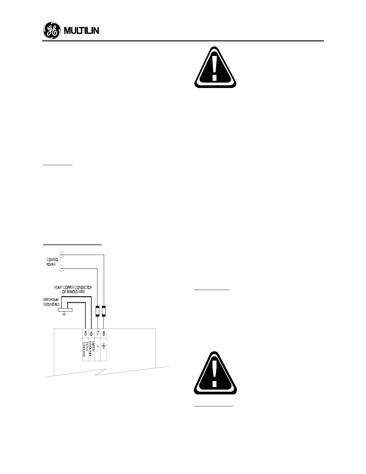
Control Power (5/6/7/8)
030
Figure 2.14 Control Power Wiring
Control power supplied to the
MPM must match the installed
power supply. If the applied
voltage does not match, damage
to the unit may occur.
A universal AC/DC power supply is standard. It
covers the range 90 - 300 VDC and 70 - 265 VAC
50/60 Hz. It is not necessary to make any adjustment
to the MPM as long as the control voltage falls within
this range. A low voltage power supply is available as
an option. It covers the range 20 - 60 VDC and 20 -
48 VAC 50/60 Hz. Verify from the product
identification label on the back of the MPM that the
control voltage matches the intended application.
Connect the control voltage input to a stable source
of supply for reliable operation. A 2 amp fuse is
accessible from the back of the MPM by sliding back
the fuse access door. Using #8 gauge wire or ground
braid, connect terminals 5 & 6 to a solid system
ground which is typically a copper bus in the
switchgear. Extensive filtering and transient
protection is built into the MPM to ensure reliable
operation under harsh industrial operating
environments. Transient energy must be conducted
back to the source through filter ground terminal 5.
The filter ground terminal (5) is separated from the
safety ground terminal (6) to allow dielectric testing of
switchgear with a MPM wired up. Connections to the
filter ground terminal must be removed during
dielectric testing.
When properly installed, the MPM will meet the
interference immunity requirements of IEC 801 and
ANSI C37.90.1.
VT Inputs (1-4)
The MPM can accept input voltages from 0 - 600VAC
between the voltage inputs (V
1
, V
2
, V
3
) and voltage
common (Vn). These inputs can be directly
connected or supplied via external VTs. If voltages
greater than 600VAC are to be measured, external
VTs are required. When measuring line to line
quantities using inputs V
1
, V
2
and V
3
, ensure that the
voltage common input Vn is grounded. This input is
used as a reference for measuring the voltage inputs.
All connections to the MPM
voltage inputs should be
connected using HRC fuses with
a 2 AMP rating to ensure
adequate interrupting capacity.
CT Inputs (9-20)
5 amp or 1 amp current transformer secondaries can
be used with the MPM for phase and neutral sensing.
Each current input has 3 terminals: 5 amp input, 1
amp input and common. Select either the 1 amp or 5
amp terminal and common to match the phase CT
 Loading...


