2 INSTALLATION
2-6
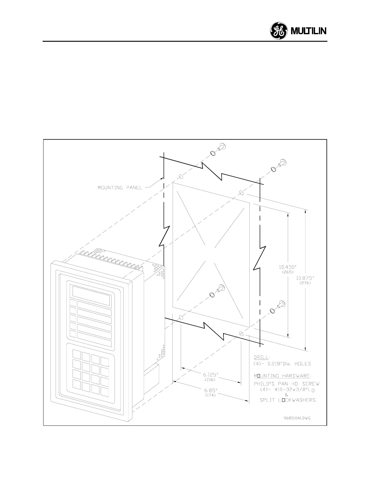
2.2 Mounting
The 269 should be positioned so that the display is
visible and the front panel keypad is accessible. A
cut-out is made in the mounting panel and the unit is
mounted as shown in Figure 2.3. Four washers and
10-32 × 3/8" mounting screws are provided.
Although the 269 circuitry is internally shielded, to
minimize noise pickup and interference the relay
should be placed away from high current conductors
or sources of strong magnetic fields. Connections to
the relay are made through terminal blocks and CTs
located on the rear of the unit.
2.3 External Connections
The connections made to the 269 relay will vary
depending on the programming of the unit. It is not
necessary to use all of the connections provided; a
minimal configuration would include supply power,
three phase current CT inputs and the Trip relay
contacts wired in series with the contactor control
relay or circuit breaker shunt trip coil. Connections to
these and the other terminals outlined below will be
explained in the following sections.
Figure 2.3
Relay Mounting
 Loading...


