3–6 MULTILINK ML2400 ETHERNET COMMUNICATIONS SWITCH – INSTRUCTION MANUAL
INSTALLATION CHAPTER 3: INSTALLATION
3.3 Mechanical Installation
3.3.1 Table-top or Shelf Mounting
The MultiLink ML2400-AC Ethernet Switch can be mounted on a table-top or any suitable
horizontal surface. It has four rubber feet to provide stability without scratching finished
surfaces.
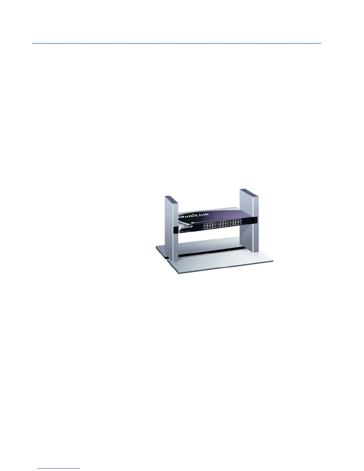
3.3.2 Rack Mounting
Installation of a MultiLink ML2400 Ethernet Switch in a 19-inch rack is a simple procedure.
The units are 1 U (1.70") high. When properly installed, the front-mounted LED status
indicators should be in plain view and easy to read. Rack-mount installation requires
special 19-inch rack-mounted brackets and screws (included with the ML2400). These
brackets attach to the front sides of the switch, which is then typically fastened into a
standard 19" RETMA rack as shown below.
FIGURE 3–1: Rack mounting
The 23-inch brackets and the ETSI (European metric, approximately 21") brackets are also
available for rack-mounting of the ML2400. These brackets are popular in the
telecommunications industry where they are a standard for central office rack-mounting
purposes. The 23-inch and the ETSI brackets are mainly used for larger equipment
assemblies in rack-mounting frames where the rack-mount equipment is typically
accessed in operation from both sides.
754733A1.CDR
 Loading...