Installation
Installation of stress- sh ield s
on the interrupting chambers
GE Information L31- 669EN/03
3/4
02- 2017
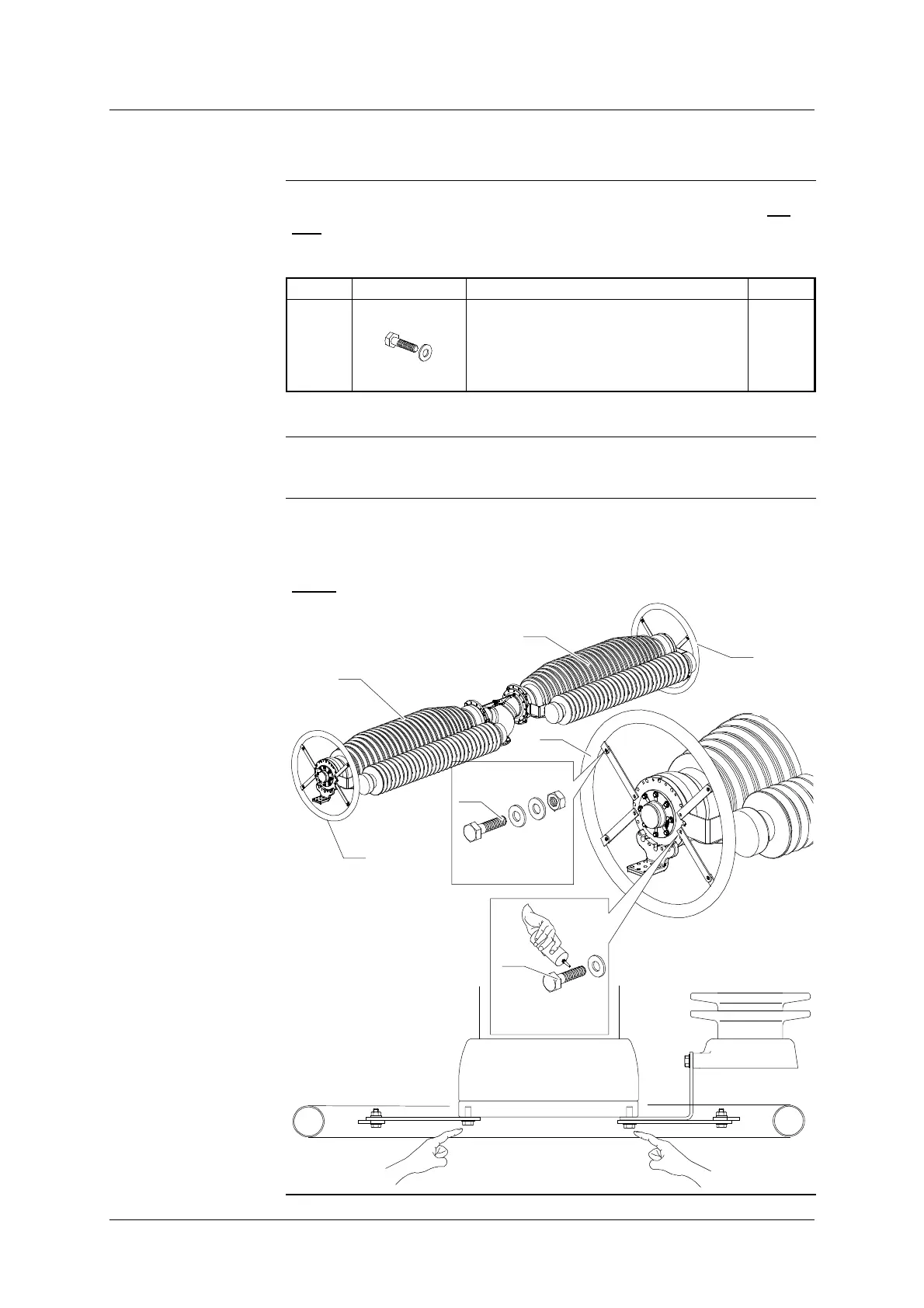
Installing stress- sh ield s
Necessary
Grid Solutions
components
List of the Grid Solutions components necessary for the assembling (
per
pole
):
Mark Diagram Designation Number
(5)
Screws
H M12-30
8
Necessary product
LOCTITE 262 (screws locking)
Process
Install the stress- shields (1) at each end of the interrupting chambers (4)
using the screws (5).
NOTE
: Lock the screws (5) with “LOCTITE 262”.
1
x4
HM10-30
3,2 daN.m
5
x4
HM12-30
5daN.m
5
1
1
4
4
 Loading...