 Loading...
Do you have a question about the GE WHRE5550K and is the answer not in the manual?
| Brand | GE |
|---|---|
| Model | WHRE5550K |
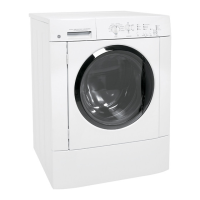
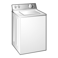
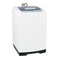
| Washer Type | Top Load |
| Color | White |
| Spin Speed | 700 RPM |
| Energy Star Certified | Yes |
| Control Type | Electronic |
| Number of Wash Cycles | 12 |
| Voltage | 120V |
| Wash Options | Extra Rinse |
| Width | 27 in |
| Height | 44 in |
Guidelines for service personnel regarding safe operation and potential risks.
Advises disconnecting power before servicing and reconnecting grounding devices.
Explains how the first two numbers of the serial number identify the month and year of manufacture.
Highlights features like HydroWave, capacity, ENERGY STAR, auto fill, variable speed motor, and counterweight.
Details the 120-VAC input powering a 3-phase induction inverter/motor assembly for speed control.
Explains the green LED on the inverter for displaying motor status via flash codes.
Describes how the shaft and tube transfer power from the drive belt to the wash system.
Explains how the mode shifter changes the shaft and tube between spin and agitation modes.
Diagram showing the mode shifter coil energized for agitate mode with cam disengaged.
Diagram showing the mode shifter coil de-energized for spin/idle mode with cam engaged.
Details the mode shifter's role in agitation, including the 18-sec program and continuous 30 VDC supply.
Explains the 30-second mode shifter spin program to engage the drive pulley for spin cycles.
Details how the agitator moves clothes, water level, stroke profile, and speed.
Details how the infusor moves clothes directly, requiring less water, and its stroke profile.
Explains how auto load sensing uses the pressure switch to determine load size and fill timing.
Diagrams illustrating water levels for Small, Large, and Super load sizes.
Details manual and automatic load size selections, and water level differences for Infusor washers.
Describes temperature selection, PerfecTemp, and TAP COLD features for wash cycles.
Details options like Autosoak, 2nd Rinse, Extended Spin, and Fabric Softener.
Explains how the time remaining display functions and is affected by fill time.
Guides on selecting wash cycles based on clothing type and soil level.
Diagram identifying key components visible from the front view of the washer.
Diagram identifying components within the control panel assembly.
Details the location and removal of the shipping rod for installation and service.
Instructions on adjusting the front and rear leveling legs to ensure the washer is stable.
Information on how the infusor is attached and the need to remove the softener dispenser.
Step-by-step instructions for removing the infusor, including dispenser and hex-head bolt.
Lists components accessible by removing the control panel: circuit board, switches, valve, filter, thermistor.
Instructions on how to safely place the control panel in a service position.
Details the control board's mounting, components, and connections.
Explains the detents and function of the options selector knob.
Details main control board connections, model selector plug, and removal procedure.
Provides flow rates, error conditions, and solenoid coil resistance for the water valve.
Step-by-step guide for removing the water valve, including hose and wire disconnections.
Explains how the thermistor and control regulate water fill temperature.
Chart showing target water temperatures for different ATC settings.
Step-by-step guide for removing the ATC thermistor from the fill funnel.
Explains the AC line filter's role in preventing electronic disruption and ensuring proper washer operation.
Describes how the cover/lid assembly is fastened with screws, catches, and locking tabs.
Step-by-step instructions for removing the cover/lid assembly.
Explains the 2-stage switch, its role in auto load sensing, and safety features.
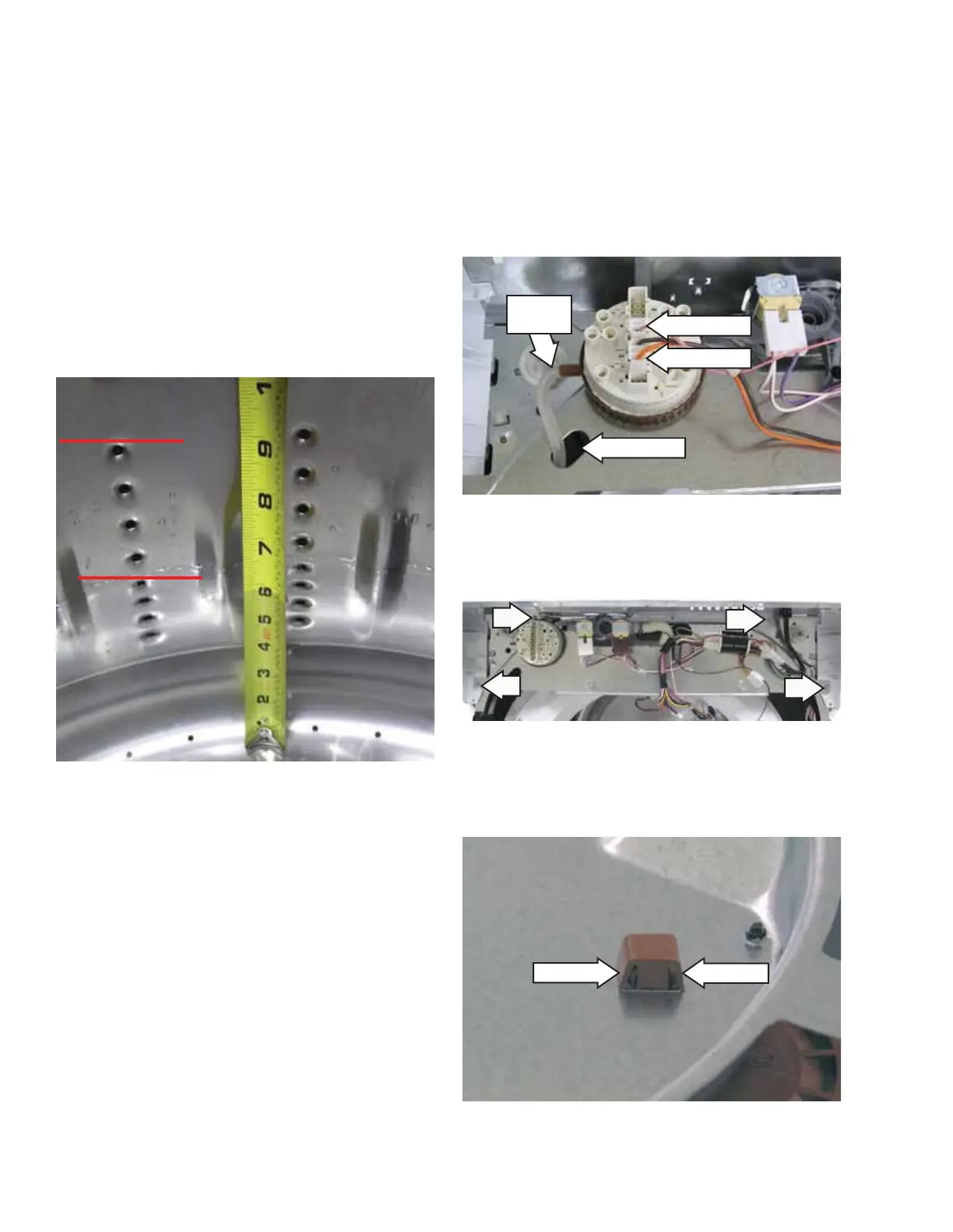
Diagram showing connections between the pressure switch and the control circuit board.
Step-by-step instructions for removing the precise fill pressure switch.
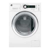
Details minimum fill volume for SMALL and SUPER settings, and water level measurements.
Explains the magnetically operated switches and their role in preventing operation when the lid is open.
Instructions for accessing and removing the lid switch assembly from the cover/lid.
Describes how the front panel is fastened with clips and tabs.
Step-by-step instructions for removing the front panel.
Provides motor specifications, resistance value, and error code conditions for the drain pump.
Explains the adaptive drain's function of sampling pump current for suds lock control and energy savings.
Notes that the belt provides constant tension with no adjustment method provided.
Explains how worn belts can cause brake time issues and motor inverter slipping belt error codes.
Recommends using a belt install tool for easier drive belt replacement.
Step-by-step guide for installing the drive belt using the specialized tool.
Notes that a new belt may be smaller and stretches to fit the pulley over time.
Explains how 120-VAC is converted to 340-VDC for speed control via PWM.
Details the motor, inverter board, brake resistor, and Hall effect sensor.
Warns against removing the inverter cover and advises caution due to high voltage and rotating parts.
Step-by-step instructions for removing the inverter/motor assembly.
Explains the 10-amp fuse's role and potential causes for its failure.
Explains the four rod and spring assemblies suspending the tub and motor assembly.
Describes the function of outer tub dampening straps to prevent excessive rotation.
Notes that the tub cover can be replaced without removing the main tub assembly.
Step-by-step instructions for removing the tub cover, including disengaging straps and tabs.
Notes that the motor can be replaced without removing the tub assembly.
Step-by-step instructions for removing the tub assembly from the cabinet.
Caution on using proper tools like rubber mallet or impact wrench for hub nut removal.
Instructions for removing the left-hand thread hub nut using an impact wrench.
Steps to disconnect motor harness connectors and platform ground wire.
Details the assembly components and warns against disassembling it.
Steps to remove the tub assembly, split ring, and washers before removing the assembly.
Instructions for disengaging front and rear rod and spring assemblies from the platform.
Steps to pull tub towards front, remove basket, and lift tub assembly from cabinet.
Instruction to remove flood hose tie and disconnect mode shifter coil harness.
Instructions for removing the drive pulley from the shaft and mode shifter assembly.
Instructions to remove platform bolts and tub bearing washer.
Instructions for removing inverted bolt and lifting the shaft and mode shifter assembly.
Step-by-step guide to enter the washer's field service mode.
Explains how to use the field service mode chart to interpret LED and display indicators.
Explains the 2-digit display and 3 LEDs (Soak, Wash, Rinse) for Profile models.
Details how to interpret knob positions, LED active modes, and corresponding functions/errors.
Details error codes for EEPROM, Thermistor, Pump, Fill, and Push Button errors.
Explains how knob positions 4-9 activate specific components like valves, pump, and spin.
Describes how to toggle and set pump time from 3 ft to 8 ft for drain out.
Outlines various methods to exit the field service mode, including timeouts and manual exit.
Describes the LED located beneath the inverter cover for diagnostic testing.
Details LED blinking rates for normal operation (standby, running) and error conditions.
Table listing error codes by number of flashes and corresponding actions like replace motor or check belt.
Details conditions for errors like excessive stop time, slipping belt, mode shifter failure, and lid errors.
Instructions for clearing errors by disconnecting power and cycling the lid.
Provides voltage readings for various pins during testing, including Gnd, N, and AC/DC voltages.
Details how to perform a spin test in field service mode and what checks to perform.
Provides voltage readings for low and high agitate tests in field service mode.
Details connecting to C7 and checking resistance for the mode shift coil.
Explains brake test criteria based on tub stopping time and consequences of brake resistor failure.
Provides an overview of the electrical schematic, including warnings and notes.
Chart detailing wire color codes and their corresponding letters and colors.
Details warranty periods for parts and labor, including limitations and specific component coverage.
Lists exclusions from warranty coverage, such as improper installation or accidental damage.
Excludes implied warranties of merchantability or fitness, limiting remedy to product repair.