- 49 -
Motherboard Components
Chapter 4 Motherboard Components
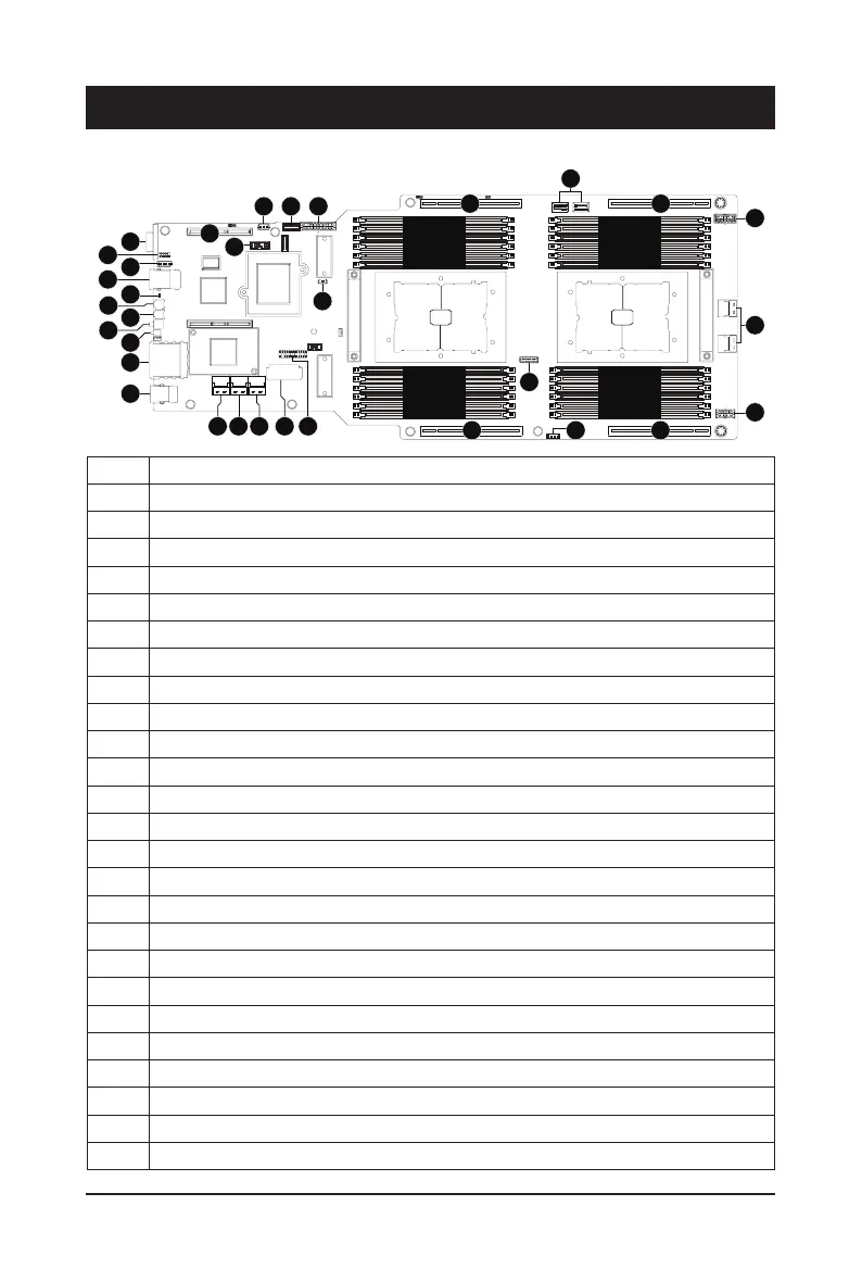
4-1 Motherboard Components
Item Description
1 Rear VGA Port
2 Serial Port Header
3 IPMB Connector
4 10/100/1000 Server management LAN port
5 BMC Firmware Readiness LED
6 Power Button with LED
7 ID Button with LED
8 Reset Button (Top)/ NMI Button (Bottom)
9 System Status LED
10 10GbE LAN Port #1/#2
11 USB 3.0 Port x 2
12 SlimLine 4i Connector (sSATA #0-#3)
13 SlimLine 4i Connector (SATA #0-#3)
14 SlimLine 4i Connector (sSATA #4-#7)
15 2 x 9 Pin Power Connector (for CPU0)
16 Front Panel Header (Primary)
17 PCIe x16 Slot #2 (Gen4 x16)
18 2 x 15 HDD Back Plane Board Connector
19 VROC RAID Upgrade Key
20 PCIe x16 Slot #4 (Gen4 x16)
21 2 x 4 Pin Power Connector (for CPU1)
22 SlimLine 4i Connectors (U2_P1_PE3A/B, support NVMe)
23 2 x 5 Pin Power Connector (for CPU1)
24 PCIe x16 Slot #3 (Gen4 x16)
25 SlimLine 4i Connectors (U2_P0_PE1A/B, support NVMe)
CPU0 CPU1
DIMM_P0_F0
DIMM_P0_E0
DIMM_P0_E1
DIMM_P0_H0
DIMM_P0_G0
DIMM_P0_G1
DIMM_P0_C1
DIMM_P0_C0
DIMM_P0_D0
DIMM_P0_A1
DIMM_P0_A0
DIMM_P0_B0
DIMM_P1_J0
DIMM_P1_I0
DIMM_P1_I1
DIMM_P1_L0
DIMM_P1_K0
DIMM_P1_K1
DIMM_P1_O1
DIMM_P1_O0
DIMM_P1_P0
DIMM_P1_M1
DIMM_P1_M0
DIMM_P1_N0
1
7
3
4
2
5
6
8
11
1312 14 15 16
23
24
18
21
22
26
27
282930
32
9
10
31
 Loading...