- 19 - System Appearance
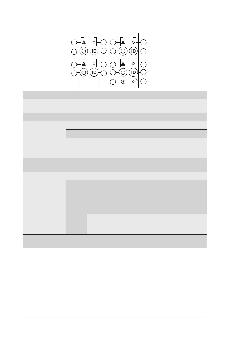
2-3 Front Panel LED and Buttons
No. Name Color Status Description
1.
System
Status LED
This LED represents the RoT function LED behavior.
Please see the following section for detail LED behavior.
2.
Reset Button -- -- Press this button to reset the system.
3.
Power button
with LED
Green On System is powered on
Green Blink System is in ACPI S1 state (sleep mode)
N/A Off
• System is not powered on or in ACPI S5 state (power
off)
• System is in ACPI S4 state (hibernate mode)
4.
ID Button
with LED
This LED represents the RoT function LED behavior.
Please see the following section for detail LED behavior.
5.
Enclosure
Green On System is operating normally.
Amber
On
Critical condition, may indicates:
Power module failure
System fan failure
Power supply voltage issue
System temperature
Blink
Non-critical condition, may indicates:
Redundant power module failure
Temperature and voltage issue
6.
CMC
Reset Button
-- -- Press this button to reset the CMC.
NODE1
RST
NODE2
RST
NODE3
RST
NODE4
RST
RST
C
4
3
1 1
3
1
2
2
3
4
6
5
1
2
4
3
2
4
 Loading...