Supplied By www.heating spares.co Tel. 0161 620 6677
23
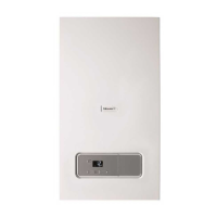
Diagram 9.5
12929
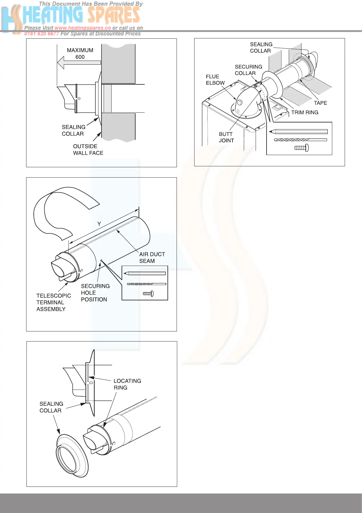
Diagram 9.6
12977
Diagram 9.7
13018
9.5 Top Horizontal Rear flue - Standard
Part No. A2043400. Refer to diagram 9.8 for
kit contents.
9.6 Flue Length
If a wall thickness of 75 min. to 507 max. is available the Top
horizontal rear flue - standard can be used without extensions.
If the wall thickness is greater than 507 then using extensions
a maximum horizontal flue length of 8 metres plus the Top
horizontal rear flue - standard can be achieved. However, for
every 90
o
or
45
o
elbows used the flue length MUST be reduced
by 1 metre.
When extension pipes are used the flue system must be
designed to have a continuous fall to the boiler of at least
44mm/metre (2.5°) to allow condensate to run back into the
boiler and out via the drain.
Remove the top flue outlet cover secured with four screws,
see diagram 9.2.
Temporarily fit the flue elbow, measure the distance from the
outside wall to flue elbow. If the measurement ‘Y’
exceeds
652mm, then the appropriate length of extension pipe is
required. The minimum dimension is 187 to suit a 75 min. wall
thickness, see diagram 9.3.
9.7 Flue Fitting
Remove the flue elbow.
Separate the flue duct from the terminal by twisting to release
the terminal catch, then pull out of the retaining seal, refer to
diagram 9.9.
The flue duct cutting length (L + 11mm.) is shown in diagram
9.9.
The air duct should be cut at the opposite end to the terminal
The plastic flue duct MUST be cut at the opposite end to the
terminal catch.
The plastic flue duct extensions MUST be cut at the opposite
end to the seal.
Diagram 9.4
12979
9 Flue Preparation and Installation
 Loading...