Supplied By www.heating spares.co Tel. 0161 620 6677
31
9 Flue Preparation and Installation
9.19 Twin flue
The twin flue system is available as an option when the top
horizontal, rear or vertical flue system is not appropriate.
The system can provide an independent horizontal air inlet
and flue outlet, horizontal air inlet and vertical flue outlet or
vertical air inlet and flue outlet via a concentric terminal.
NOTE: The air and flue outlets do not have to be equal
lengths. 2x45° bends can replace 1x90° bend if necessary.
The maximum permitted straight pipe length is 40 metres plus
terminal assemblies, for each 90°
or 45°
x 2 bends fitted, the
maximum length must be reduced by 1 metre.
NOTE: When using 90° bends any horizontal run should be
inclined by a minimum of 44mm/metre (2.5°) towards the
boiler to facilitate condense removal.
Alternatively use 45° bends to avoid horizontal runs in the flue
pipe.
Terminal Position
The clearances for a flue outlet are given in the "Flue Location
and Ventilation" section.
In addition the horizontal air inlet must not be closer than 300
mm from a flue outlet on the same wall or 1200mm from an
opposing fl
ue outlet.
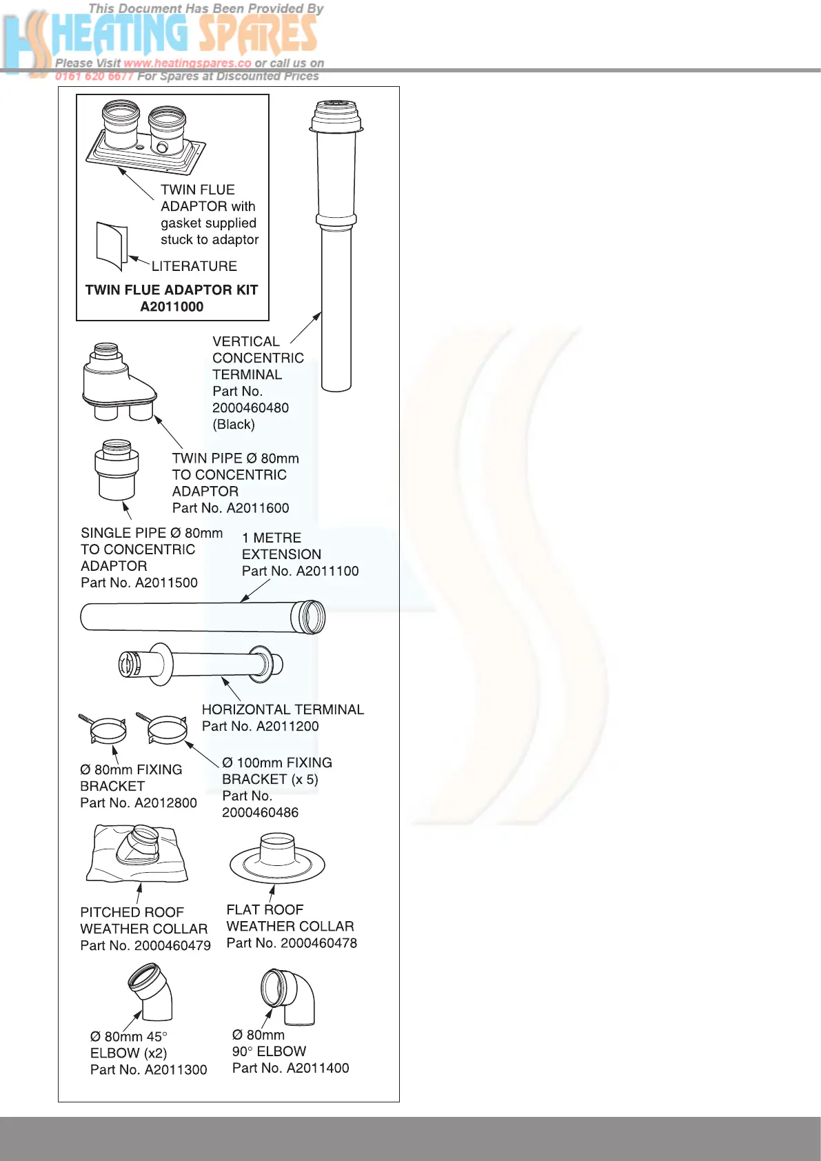
Installation Details
The parts available for a twin flue system installation are
shown in diagram 9.23.
Boiler Connection
Remove the top flue outlet cover secured with four screws,
see diagram 9.2.
Push the twin flue adaptor onto the outlet of the boiler with the
air inlet to the left hand side. Secure the adaptor to the top
panel with the screws provided. Care should be taken when
inserting the screw through the hole in adaptor top.
T
o facilitate engagement, it is recommended that the rubber
‘O’ rings are lubricated with silicone grease or water prior to
assembly.
See diagram 9.24.
Air and Flue Pipe Installation
The air and flue pipes can now be built up from the boiler.
The flue must be designed with a continuous fall towards the
boiler. If using the horizontal flue pipe or 90° bends the pipe
must be inclined at 44mm/metre (2.5°)
minimum, see diagram
9.25.
Alternatively if space allows, use 45° bends in place of 90º
bends.
The rubber ‘O’ rings of each section should be lubricated prior
to assembly with silicone grease.
When building the flue up it is recommended that it is sup-
ported every 2 metres and at every bend by a fixing bracket.
Diagram 9.23
12970
 Loading...