Supplied By www.heating spares.co Tel. 0161 620 6677
37
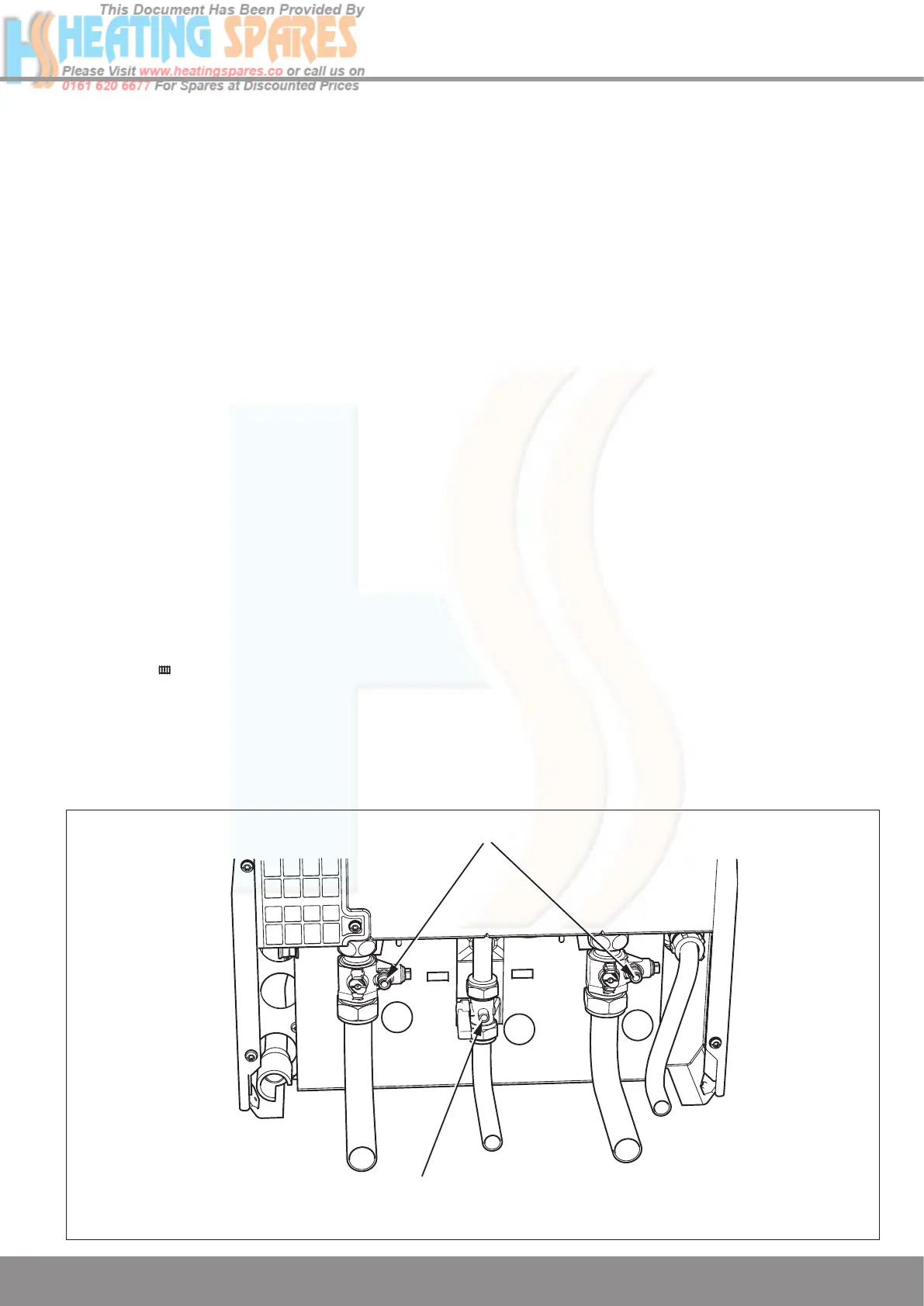
DRAIN POINTS
A
B
A
PRESSURE
TEST POINT
11 Commissioning
11.1 System Commissioning
Pre-filling the system
Once the system pipework has been completed it is possible
to pre fill the system before mounting the boiler if so desired.
Ensure that the isolation valves are securely tightened into the
jig blanking plugs, see diagram 11.2.
Refer to diagram 11.1 and open the CH isolation valves ‘A’ by
using a screwdriver or a 4mm allen key ensuring that the slot
is in line with the axis of the cock (shown closed in diagram).
NOTE: A manometer kit accessory, part no. 0020016995 is
available to monitor system pressure during filling if required.
This should be attached to the drain point of one of the CH
isolation valves and the drain point opened to enable a
reading of the system pressure to be taken.
Fill the system until a fill pressure of approximately 1.0 bar is
achieved.
Vent all air from the system and repeat the filling procedure
until the system is full and all air has been removed.
Check system soundness.
Close the drain point.
To comply with the water regulations the remotely installed
filling loop connection must be removed.
When the appliance has been installed:
1. Open the two central heating isolating valves marked ‘A’
so that the slots are in line with the length of the valve
(shown closed in diagram 11.1).
2. Turn the mains electricity supply on to the appliance.
Set the Central Heating temperature to OFF by pressing
the MODE button on the User Interface until it shows
the symbol
and then pressing the - (minus)
SELECTOR button.
The display will now permanently show system pressure.
3. Pressurise the system until the pressure on the display
reads at least 1.0bar.
4. Vent all air from the system - repeat step 3 as neccessary
until the system is full and all the air has been removed.
5. After filling is complete set the Central Heating temperature
to the desired level using the MODE and + (plus)
SELECTOR buttons as described above.
11.2 Preparation for Lighting
Isolate the boiler from the mains electrical supply.
Test for gas soundness and purge air from the gas supply.
Turn on the gas isolation valve marked ‘B’ so that the slot is in
line with the length of the valve, see diagram 11.1.
11.3 Initial Lighting
The lighting procedure of the boiler is fully automated.
Check that all external controls are calling for heat.
The digital display will show water temperature in central
heating demand. The appliance will enter a self checking
routine then the fan should start and the ignition will
commence.
If the burner fails to light the fan will stop. Initially this may be
due to air in the gas supply line. The boiler will automatically
have five attempts at ignition.
If the burner fails to ignite the display will show F1.
Depress the ‘reset’ button on the fascia to clear the display
and repeat the ignition sequence.
Set the Central heating temperature to the desired
temperature by by using the MODE and + (plus) or - (minus)
SELECTOR buttons.
The appliance will then continue to fire in central heating
mode until the user controls are satisfied.
NOTE: After ignition the boiler will ramp slowly to full rate
rather than going immediately to full rate. This is an adaptive
feature to cope with small system requirements.
Diagram 11.1
13057
A - Central Heating Isolation Valve
B - Gas Service Cock
 Loading...