PLATE
JIG PLATE
7 Gas / Water Connections
13039
Diagram 7.2
7.1 System connection
NOTE: The Gas and Water systems can be connected
and lled prior to installation of boiler, refer to section 12
Commissioning. Make sure the drain points are accessible,
refer diagram 5.5.
All water and gas connections are on the xing jig with the
exception of the condense drain and safety discharge, the
positions of these are shown on the wall template.
An Upward Piping Frame, part no. A2041500 should be used
if the supplies come from above the boiler otherwise the pipes
will have to be chased into the wall.
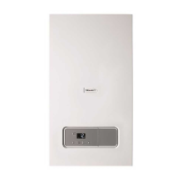
Assemble the pipes to the jig as shown in diagram 7.1.
Fit the Central Heating Isolation Valve handles and secure
with screws provided.
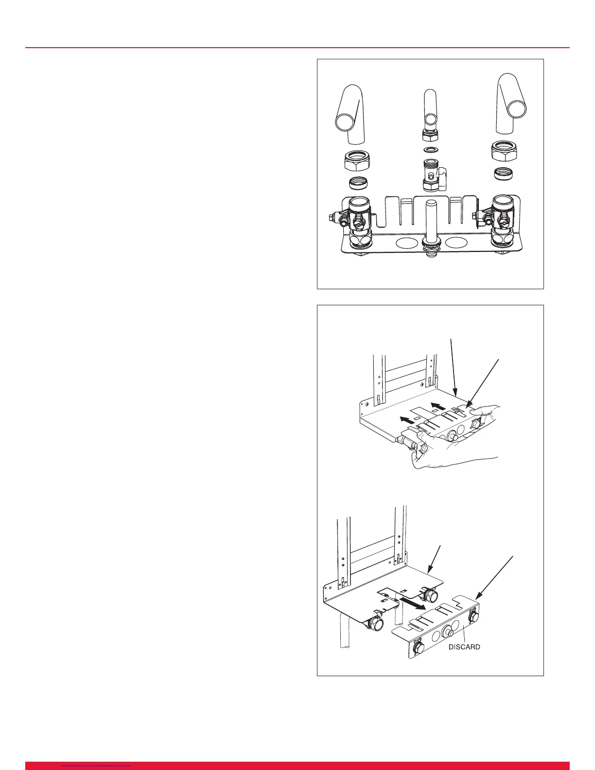
Fit the assembled Jig Plate to the Support Plate as shown in
diagram 7.2.
Assemble the Gas service isolation valve and position onto
the plastic plug.
Plumb system pipe work to the copper tails. Do not subject
isolation valves to heat.
Prior to lling the water system ensure that the blanking plugs
and isolation valves are secured.
Flush out the domestic hot water and the heating systems.
The whole of the gas installation, including the meter, should
be inspected, tested for soundness and purged in accordance
with the current issue of BS6891 and in IE the current edition
of I.S.813 “Domestic Gas Installations”.
14025
Diagram 7.1
 Loading...