39
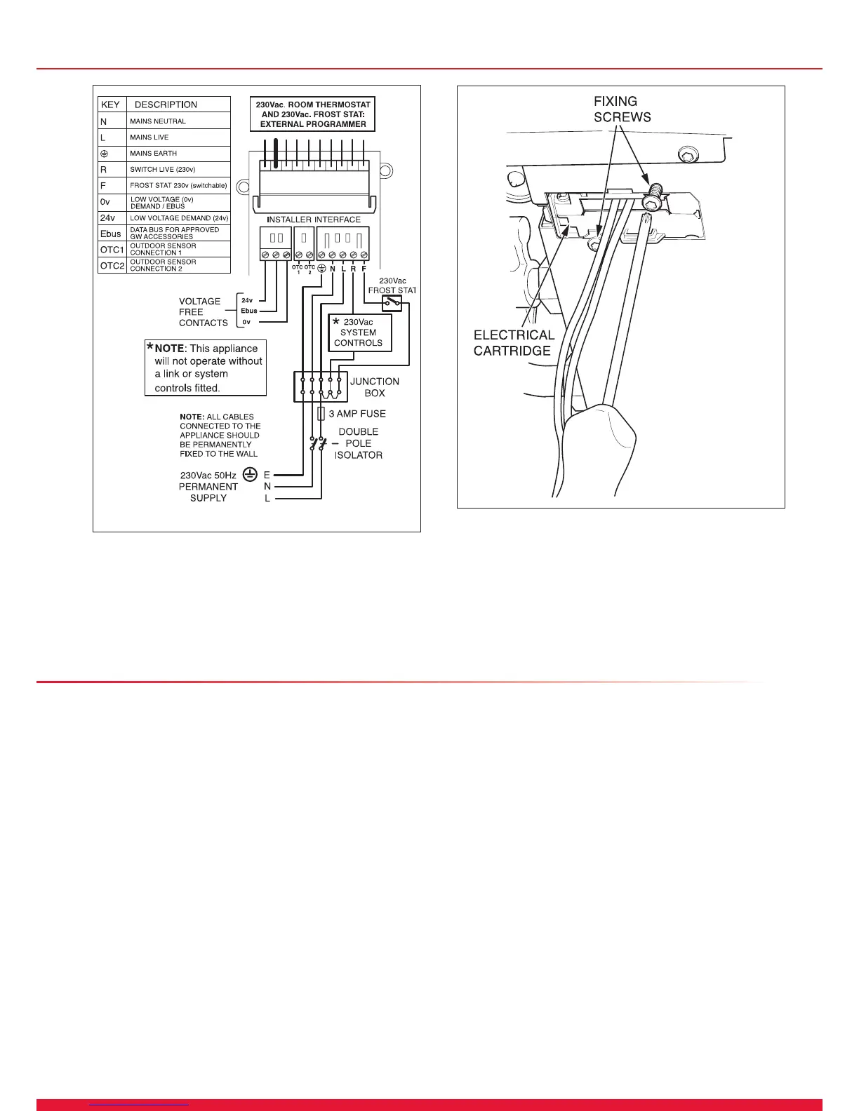
11.5 Electrical Cartridge Securing
Fit electrical cartridge into the interface housing on completion
of the wiring, see diagram 11.4.
Secure with the two cartridge retaining screws provided in the
cartridge body.
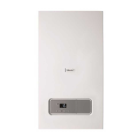
11 Electrical Connection
Diagram 11.3
13369
Diagram 11.4
13922
11.6 Electrical Connections - Testing
Carry out preliminary electrical system checks as below:
1. Test insulation resistance to earth of mains cables.
2. Test the earth continuity and short circuit of cables.
3. Test the polarity of the mains.
NOTE: If you require to test the appliance refer to section 14.
12 Commissioning
IMPORTANT: At the time of commissioning, complete all
relevant sections of the Benchmark Checklist located in the
centre pages of this document.
12.1 Pre-lling the Heating Circuit
Do Not operate the boiler without water.
The commissioning should be carried out by a competent
person approved at the time by the Health and Safety
Executive and in accordance with the current issue of
BS6798.
Make sure that the system has been thoroughly ushed
out with cold water and that all cleanser if used has been
removed.
With the gas service isolation valve closed, with no demand
from any external controls and the power supply to the boiler
switched off.
Test for gas tightness and purge air from the gas supply.
Refer to diagram 12.1
1. Once the system pipework has been completed it is
possible to pre ll the system before mounting the boiler if
so desired.
2. Ensure that the isolation valves are securely tightened into
the jig blanking plugs, see diagram 12.1.
3. Refer to diagram 12.2 and open the CH isolation valves
‘A’ by using a screwdriver or a 4mm allen key ensuring that
the slot is in line with the axis of the cock (shown closed in
diagram).
NOTE: A manometer kit accessory, part no. 0020016995 is
available to monitor system pressure during lling if required.
This should be attached to the drain point of one of the CH
isolation valves and the drain point opened to enable a
reading of the system pressure to be taken.
Fill the system until a ll pressure of approximately 1.0 bar
is achieved. Vent all air from the system and repeat the
lling procedure until the system is full and all air has been
removed. Check system soundness. Close the drain point.
To comply with the water regulations the remotely installed
lling loop connection must be removed.
 Loading...