38
WARNING: This appliance must be earthed.
● This appliance must be wired in accordance with these
instructions. Any fault arising from incorrect wiring cannot be
put right under the terms of the Glow-worm guarantee.
● All system components must be of an approved type.
Electrical components have been tested to meet the
equivalent requirements of the BEAB.
● Do not interrupt the mains supply with a time switch or
programmer.
● Connection of the whole electrical system and any heating
system controls to the electrical supply must be through a
common isolator.
● Isolation should preferably be by a double pole switched
fused spur box having a minimum contact separation of
3mm on each pole. The fused spur box should be readily
accessible and preferably adjacent to the boiler. It should be
identied as to its use.
● A fused three pin plug and shuttered socket outlet may be
used instead of a fused spur box provided that it is not used in
a room containing a xed bath or shower.
● The boiler is suitable for installation in bathroom zones 2
and 3.
11.1 Electrical Wiring
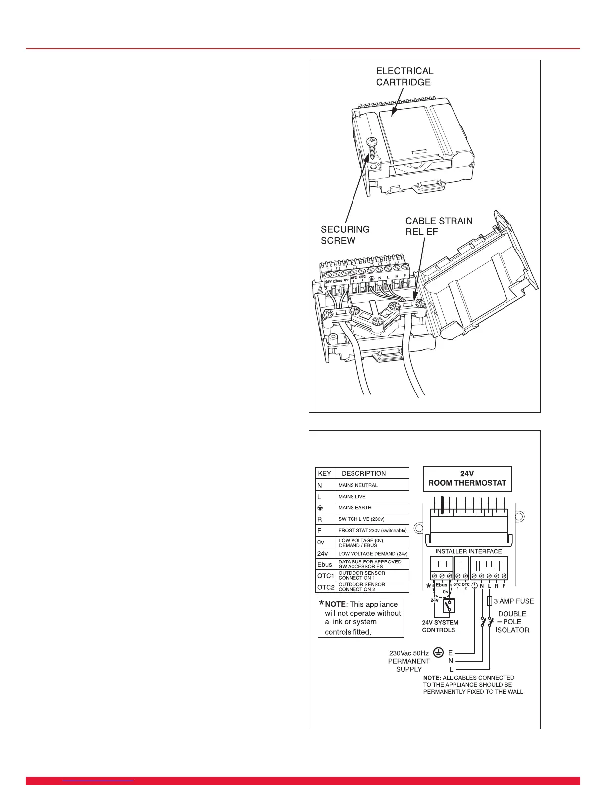
Remove the electrical cartridge from the ttings pack.
Remove the securing screw to open the cartridge.
NOTE: There are two screws supplied loose in the electrical
cartridge, these will be required to secure the cartridge into
the electrical interface housing.
Slacken the screws of the cable strain relief in the electrical
cartridge, see diagram 11.1.
Route the mains supply and system cables through the strain
relief and connect to the relevant plug, refer to the appropriate
sections 11.2 or 11.3.
Initially, if system controls are not tted, leave the “Red Link”
in place, this will create a continuous demand.
11.2 System Controls 24V
WARNING: UNDER NO CIRCUMSTANCES MUST
ANY MAINS VOLTAGE BE APPLIED TO ANY OF THE
TERMINALS ON THE 24V CONNECTION PLUG.
Connect the mains supply and system heating controls e.g.
room thermostat as diagram 11.2. External controls should be
tted in accordance with the rules in force.
11.4 Mains Voltage System Controls
WARNING: UNDER NO CIRCUMSTANCES MUST
ANY MAINS VOLTAGE BE APPLIED TO ANY OF THE
TERMINALS ON THE 24V CONNECTION PLUG.
Connect mains supply and system controls as diagram 11.3.
External controls should be tted in accordance with the rules
in force.
13921
Diagram 11.1
11 Electrical Connection
Diagram 11.2
13368
 Loading...