44
13 Servicing
1. Maximum Rate Check and Adjustment
NOTE: To verify the maximum gas rate CO2 setting the
appliance must be checked at the maximum rate rst.
Press the “reset” button on the controls fascia, release
and immediately press and hold in the “+” button. After
approximately 5 seconds “Hi” will be displayed. Pressing
the mode button when “Hi” is selected will force the boiler
to maximum rate, the display will ash between “Hi” and the
“default display” this will indicate the boiler has been forced to
maximum. Wait until the CO2 value is stable and check that
the value is within the range specied in table in the “check”
column.
If the combustion reading is not within the acceptable values
AND the integrity of the complete ue system and combustion
circuit seals have been veried and the inlet gas pressure
(and gas rate) have been veried, then, it will necessary to
adjust the combustion rate of the appliance.
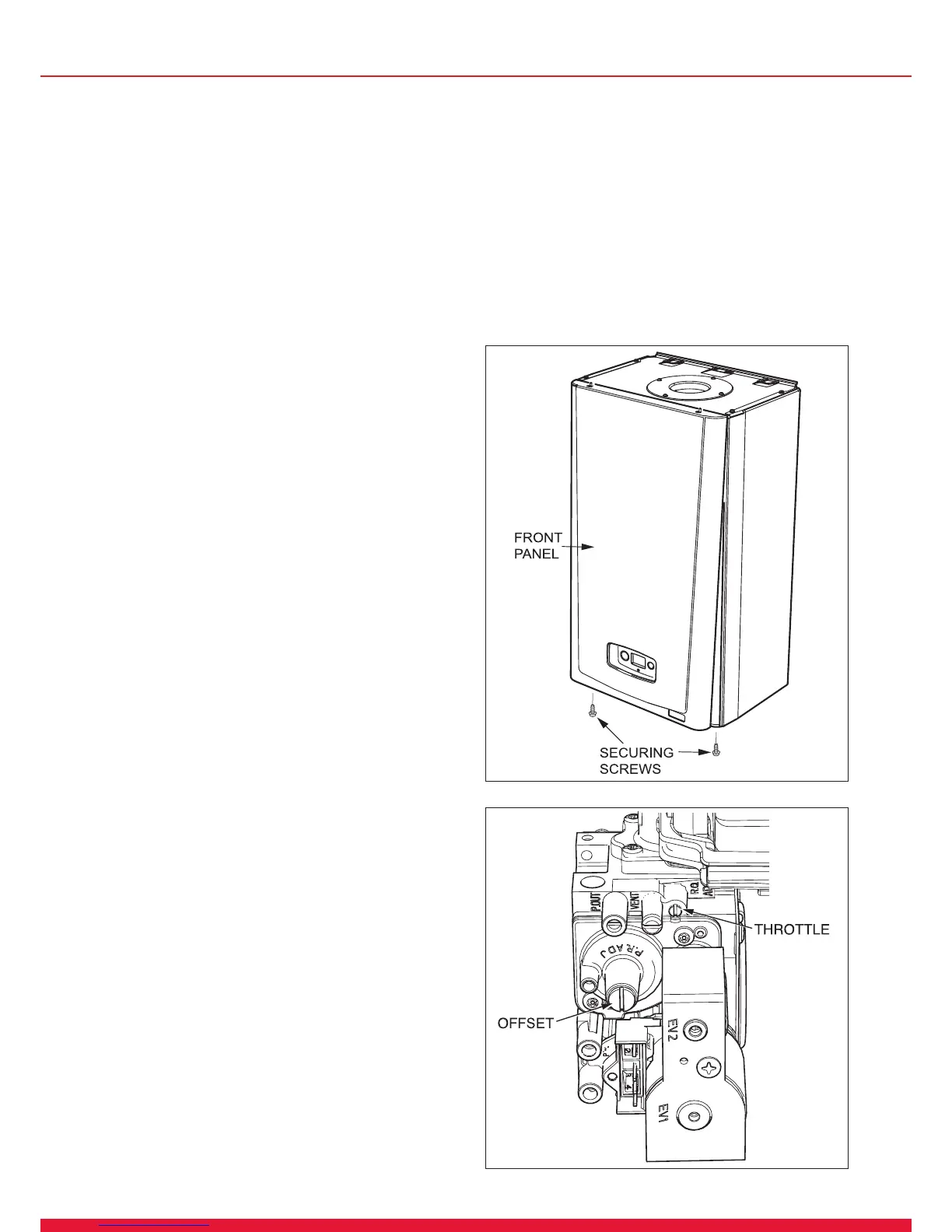
NOTE: Adjustment is made by turning the gas valve
throttle an ⅛ of a turn, waiting 1 minute to allow the
appliance to stabilise before checking or making further
adjustments.
● Rotate the “throttle”(anti-clockwise to increase), to the
required CO2, refer to diagram 13.3 and the “SETTING”
column in the table.
● Exit the forced rate function, press the “mode” and “+”
buttons simultaneously, this will reset the boiler to the default
display. Now proceed to check the minimum rate adjustment.
2. Minimum Rate Check and Adjustment
● Now check the minimum gas rate CO2 setting: Press
and release the “reset” button on the controls fascia, then
immediately press and hold in either of the “+” buttons. After
approximately 5 seconds “Hi” will be displayed. Pressing the
“+” or “-” buttons will toggle between “Hi” and “Lo”. Press the
mode button when “Lo” is selected, this will force the boiler
to minimum rate and the display will ash “Lo”, indicating the
boiler is operating at minimum.
● Wait until the CO2 value is stable and check that the value
is within the range specied in table in the “check” column.
If adjustment is necessary, proceed as follows:
NOTE: Adjustment of the CO2 at minimum rate is very
coarse and should not be adjusted more than an ⅛ of
a turn at a time. Wait 1 minute to allow the appliance to
stabilise before checking or making further adjustments.
● Gradually rotate the “offset adjustment” (anti-clockwise to
decrease) to the required CO2, refer to diagram 13.3 and the
“SETTING” column in the table.
● Exit the minimum rate function, press the “mode” and “+”
buttons simultaneously, this will reset the boiler to the default
display.
3. Re-Check CO2 and check the CO/CO2
combustion ratio.
● Re-check the maximum and minimum CO2 values to
ensure that they are within the “setting” limits in the table
then check the CO/CO2 combustion ratio does not exceed
the value in the CO/CO2 column of the table. If the CO/CO2
setting exceeds the value in the table, a complete servicing of
the appliance will be necessary, refer to section 13.1.
If the CO2 and the CO/CO2 ratio falls within the tolerances
quoted, exit the function press the “mode” and “+” buttons
simultaneously, this will reset the boiler to the default display.
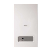
Remove the analyser probe and replace the cap on the
sampling point, replace the controls fascia, inner and front
casing panels.
IMPORTANT: Remember to replace the sample point cap on
completion of the test.
13093
Diagram 13.2
GAS RATE CHECK
Check the gas rates as described in the commissioning
section.
COMPLETION
If it is not possible to achieve the required results for either
the combustion or gas rates, it will be necessary to complete
a full service of the appliance and then repeat the combustion
check procedure. If after servicing and adjustment of the
appliance the combustion values are still unacceptable and
after further remedial work has been carried out, the appliance
must be disconnected until the CO/CO2 ratio is acceptable.
Advice can be sought from the Glow-worm Technical Helpline.
Diagram 13.3
12776
 Loading...