35
10 Twin Flue - Length, Preparation and Installation
10.15 Twin ue
The twin ue system is available as an option when the top
horizontal or vertical ue system is not appropriate.
The system can provide an independent horizontal air inlet
and ue outlet, horizontal air inlet and vertical ue outlet or
vertical air inlet and ue outlet via a concentric terminal.
The system is made up from accessories, see diagram 10.30.
NOTE: The air and ue outlets do not have to be equal
lengths. 2x45° bends can replace 1x90° bend if necessary.
The maximum permitted combined (air inlet + ue outlet) ue
length is 20 metres plus terminal assemblies. For each 90°
or
45°
x 2 bends tted, the maximum ue length must be reduced
by 1 metre, see diagram 10.29.
NOTE: When using 90° bends any horizontal run should be
inclined by a minimum of 44mm/metre (2.5°) towards the
boiler to facilitate condense removal.
Alternatively use 45° bends to avoid horizontal runs in the ue
pipe.
Multiple Boiler Chimney Flue Length
The ue length must be calculated and installed according to
the relevant standards EN 13384-1 and 2 (C43 ue systems
only) with reference to the table below and the manufacturers
instructions supplied.
The appliance maximum ue length must be included when
calculating the overall design of the ue system.
Terminal Position
The clearances for a ue outlet are given in the "Flue Location
and Ventilation" section.
In addition the horizontal air inlet must not be closer than 300
mm from a ue outlet on the same wall or 1200mm from an
opposing ue outlet.
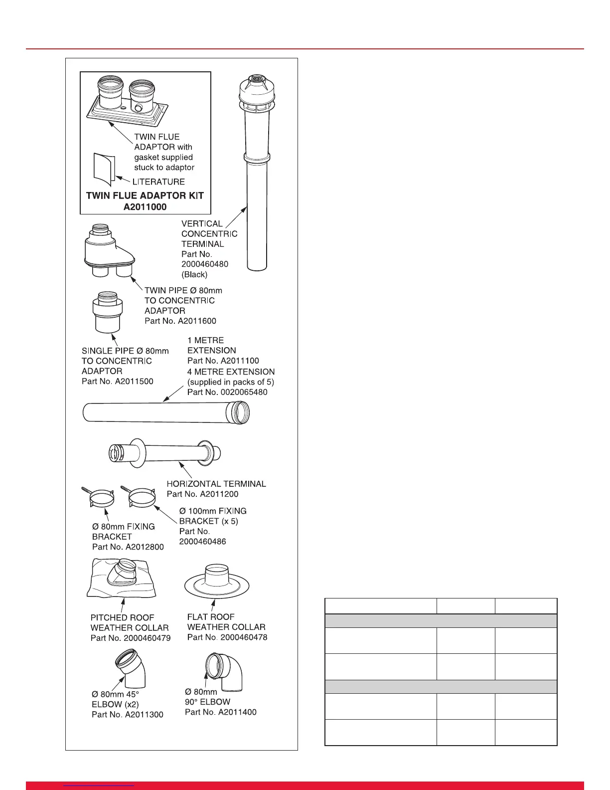
Installation Details
The parts available for a twin ue system installation are
shown in diagram 10.30.
Diagram 10.30
14869
MODEL 18sx 30sx
Exhaust mass rate (g/s)
At Min Thermal
Load (40C°/30°C)
4.26 4.26
At Max Thermal
Load (80C°/60°C)
8.24 13.95
Exhaust temperature (ºC)
At Min Thermal
Load (40C°/30°C)
33.2 33.2
At Max Thermal
Load (80C°/60°C)
63.0 87.4
 Loading...