55
15 Replacement of Parts
15.6 Gas valve
For access, refer to section 15.1.
Remove the electrical plug from the gas valve.
Undo the tubing nut holding the gas pipe to the gas valve.
Remove the three securing screws, holding the gas valve to
the fan and remove the gas valve, see diagram 13.6.
After re-tting check the combustion CO2 and adjust if
necessary, refer to section 13 Combustion Check.
After assembly test for gas soundness and purge in
accordance with the current issue of BS6891or in IE, the
current edition of I.S.813 “Domestic Gas Installations”.
15.7 Flue Hood
For access, refer to section 15.1.
Pull the ue hood securing clips away from the ue hood
sump and push ue hood up slightly towards ue hood top,
see diagram 13.4.
To remove swivel ue hood 90° and pull down and out
towards front of boiler, see diagram 13.4.
15.8 Fan
For access, refer to section 15.1.
Remove the gas valve as described in the relevant parts of
section 15.6.
Remove the securing nut holding the fan retaining bracket,
lift front of bracket away from stud and pull forward to release
the fan, see diagram 13.9, check and replace any seals or
gaskets if necessary.
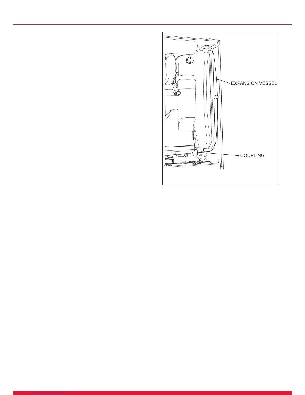
15.9 Expansion Vessel
For access, refer to section 15.1.
Drain the boiler heating circuit, refer to section 15.2.
Undo the coupling at the base of the vessel, see diagram
15.2.
Remove the locking screw and spacer from the retaining
bracket at the top of the expansion vessel. Whilst holding
and also pushing down slightly on the vessel, remove the
expansion vessel retaining bracket by unhooking and sliding
forward.
The expansion vessel can now be removed by sliding it
forward clear of its support guides.
When re-tting a new gasket will be required between the
expansion vessel and coupling.
Rell, vent and pressurise the boiler.
Check for leaks.
Diagram 15.2
15584
 Loading...