59
15 Replacement of Parts
15.19 Automatic Air Vent
For access, refer to section 15.1.
Refer to section 15.2 and drain the boiler heating circuit.
Refer to diagram 15.8.
Remove the retaining clip to release the automatic air vent.
Fit the new automatic air vent and ‘O’ ring ensuring the vent
cap is left loose.
Rell, vent and pressurise the boiler and check for leaks.
15.20 Heat Exchanger
For access, refer to section 15.1.
Remove silencer front, ue hood, gas valve / burner assembly,
igniter unit and support bracket, spark electrode lead, burner
and condense trap.
Refer to section 15.2 and drain the boiler heating circuit.
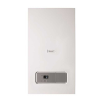
Remove the retaining clip, see diagram 15.10, which secures
the ow pipe brass elbow into the hydroblock. Remove the
retaining clip, which secures the ow pipe into the anged
elbow in the top right hand corner of the heat exchanger, see
diagram 15.11.
Remove the left hand side panel to aid removal of the copper
ow pipe. Note that the minimum clearance from the side
panel is 5mm.
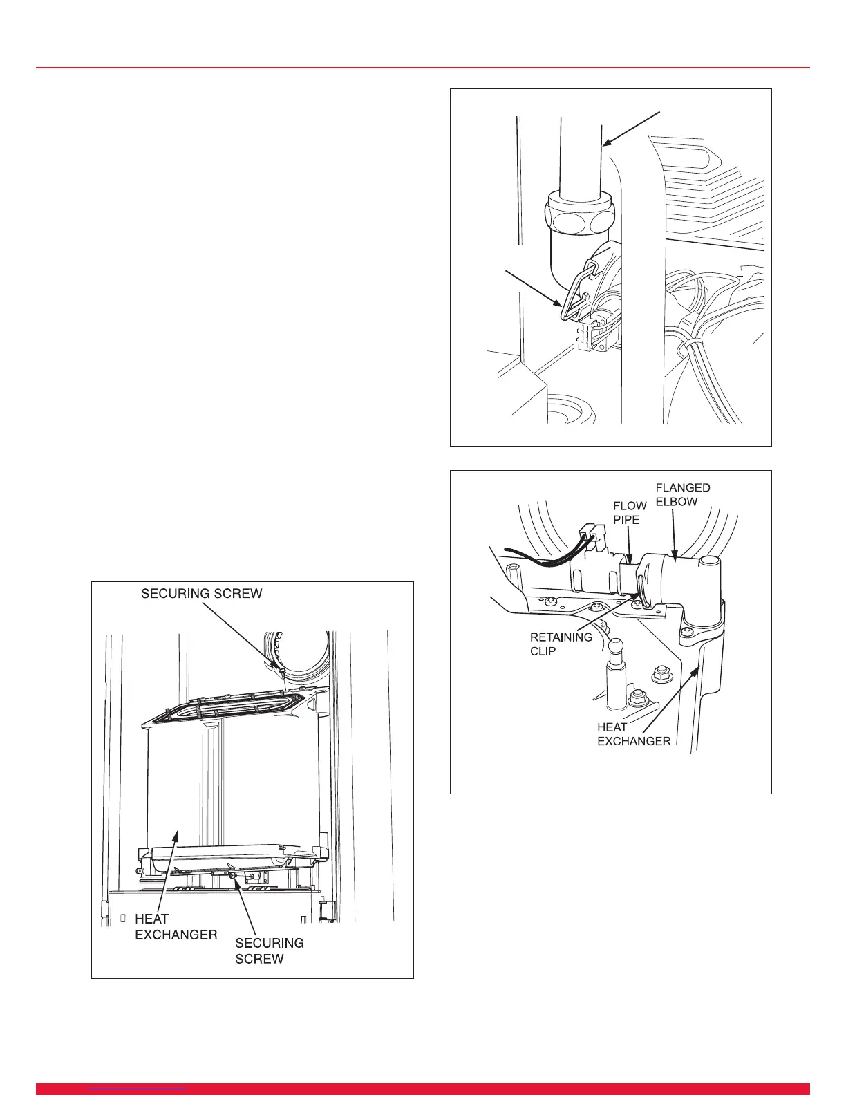
Remove screws securing the heat exchanger, one on top and
one underneath the heat exchanger, see diagram 15.9.
Undo the knurled nut at the right hand side of the hydroblock.
Remove the retaining clip from the anged elbow at the right
hand bottom of the heat exchanger. Remove the return pipe.
Lift up heat exchanger slightly to disengage it from its hanging
bracket.
Remove the heat exchanger, complete with sump, return pipe
and anged elbows, by pulling forward and tilting backwards
to ease removal.
Diagram 15.9
12812
Diagram 15.10
15589
FLOW
PIPE
RETAINING
CLIP
Diagram 15.11
15591
 Loading...