Repair
Transformer S
econdary Check
See Electrical Schematics, page 106.
1. Check wires an
d transformer:
a. Disconnect 7 pin green connector from TCM.
b. Use an ohmmeter to test for continuity
between terminals 6 and 7 on the TCM 7 pin
green connector. There should be continuity.
If there is no continuity, check transformer.
c. Reconnect 7 pin green connector to TCM
2. Check transformer:
a. Remove lower shroud.
b. Locate the two larger (6 AWG) wires,
labeled 3 and 4, coming out of transformer.
Trace these wires back to TB17 and TB18.
Open circuit breaker CB01 to turn the color
indicator on the circuit breaker GREEN. Use
an ohmmeter to test for continuity between
two transformer wires in terminal blocks
TB17 and TB18; there should be continuity.
c. Close the circuit breaker CB01.
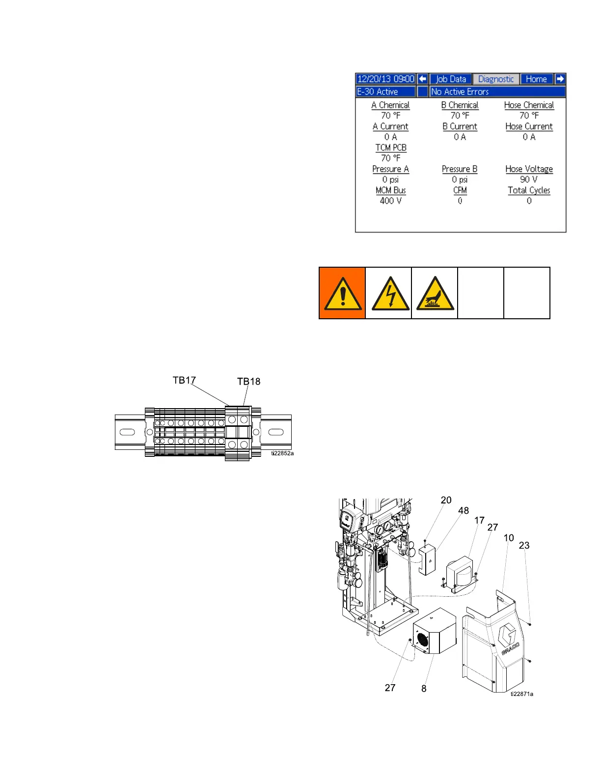
Figure 18
d. Apply incoming power to system.
e. To verify voltage on the secondary leads
of the transformer, measure between the
terminals terminals 3 and 4 on TB17 and
TB18. Verify voltage is approximately 90
VAC for 240 VAC input.
f. See the Diagnostic Run Screen on the
ADM. The Diagnostic Run Screen displays
theincoming(90Vac)totheTCM“Hose
Voltage”. The diagnostic screen will show if
the circuit breaker has been tripped for the
incoming power to the TCM.
Replace Transformer
1. Perform Shutdown, page 50.
2. Remove four bolts (23) and shroud (10).
3. Remove lower dinrail cover (48).
4. Disconnect fan and transformer connections
from terminal blocks. Connections are on left
side labeled: V+, V-, 1, 2, 3, and 4.
5. Remove four nuts (27) holding metal transformer
cover (8) to frame. Carefully remove cover while
slidingwiresthroughholeincover.
6. Remove nuts (27) and transformer (17).
7. Install transformer (17) in reverse order.
Figure 19
333024N
77
 Loading...