EN - 26
ADJUST UNIT TO DRIVE
STRAIGHT
If unit does not drive straight when steering-
lock lever is engaged, adjustments may be
necessary.
Adjust Tire Pressure
1. Place unit in service position. See
Service Position on page 18.
2. Check tire pressures. If needed, adjust to
recommended pressures. See
Specifications on page 39.
IMPORTANT: DO NOT inflate tires outside
recommended range.
3. Check tracking. If unit does not drive in
straight line, adjust steering lock. See
Adjust Steering Lock on page 26.
Adjust Steering Lock
1. Place unit in service position. See
Service Position on page 18.
2. Check tire pressures. If needed, adjust to
recommended pressures. See
Specifications on page 39.
IMPORTANT: DO NOT inflate tires outside
recommended range.
3. Disengage steering-lock lever.
4. Measure the length of each compression
spring above the lower steering plate.
Each spring length MUST measure
2.8 cm – 2.9 cm (1 3/32" – 1 5/32"). If
springs are not within specification,
tighten or loosen flange nuts as
necessary. See Figure 31.
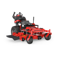
See Figure 32.
5. Adjust steering lock:
• If unit moves to the left when steering-
lock lever is engaged, loosen outer-left
and inner-right jam nuts. Tighten inner-
left and outer-right jam nuts.
• If unit moves to the right when steering-
lock lever is engaged, loosen outer-
right and inner-left jam nuts. Tighten
inner-right and outer-left jam nuts.
6. Check steering lock function and readjust
as necessary.
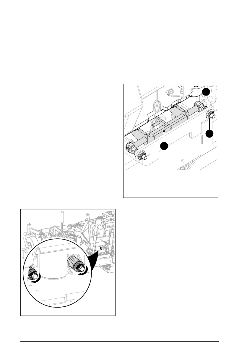
ADJUST STEERING-LOCK
CABLE
See Figure 33.
If steering-lock lever does not engage
steering lock arm, cable may need
adjustment.
1. Disengage steering-lock lever.
2. Loosen the upper jam nut and tighten the
lower jam nut until tight against cable
bracket.
3. Reposition rubber boot against
adjustment barrel.
4. Check cable adjustment and readjust as
necessary.
Figure 32
1. Steering Lock Arm
2. Inner Jam Nut
3. Outer Jam Nut
2
1
3
 Loading...