Multi VRF Indoor
Unit Service Manual
49
CONTROL
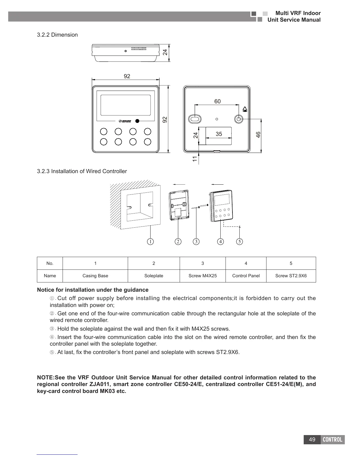
3.2.2 Dimension
92
60
35
92
24
46
11
24
3.2.3 Installation of Wired Controller
1 3 4 52
No. 1 2 3 4 5
Name Casing Base Soleplate Screw M4X25 Control Panel Screw ST2.9X6
Notice for installation under the guidance
① .
Cut off power supply before installing the electrical components;it is forbidden to carry out the
installation with power on;
② .
Get one end of the four-wire communication cable through the rectangular hole at the soleplate of the
wired remote controller.
③ .
④ .
controller panel with the soleplate together.
⑤ .
NOTE:See the VRF Outdoor Unit Service Manual for other detailed control information related to the
regional controller ZJA011, smart zone controller CE50-24/E, centralized controller CE51-24/E(M), and
key-card control board MK03 etc�

 Loading...