Multi VRF Indoor
Unit Service Manual
75
3) When the “Control Mode” is set to “L”, the “Memory Mode” and “Master/Slave Indoor Unit” is forbidden
to be set unless the “Control Mode” is then set to “I”.
4) The DIP switch shall be set exactly in position but not stay in the middle. Setting to “ON” represents “0”
of the binary system and “1” to the opposite side.
4.2.2 Address Code
The address DIP switch must be set properly for the multi VRF indoor units, otherwise it would lead to
communication trouble. The address code consists of 4 binary bits and is related to the address ranging from
1-16.
NOTES!
To use multiple indoor units in parallel, make sure to change the setting of address code before installation
and guarantee that the address code of each indoor unit must be different (The address code is located on the
mainboard of indoor unit). If wired controller is used, make sure to set the address of wired controller to the
position same as the address code on corresponding indoor unit. (The address of wired controller is located on
the back of wired controller)
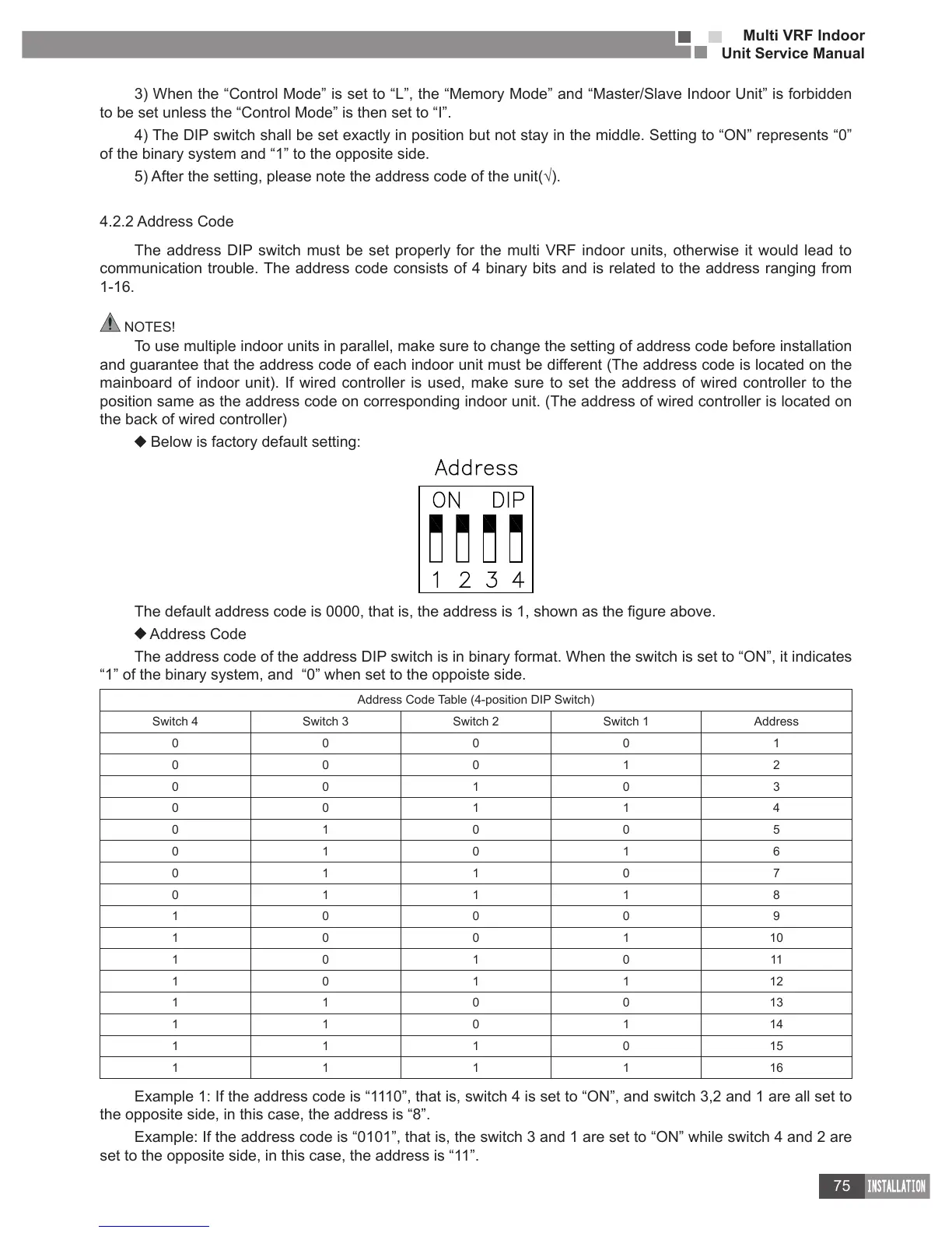
Below is factory default setting:
Address Code
The address code of the address DIP switch is in binary format. When the switch is set to “ON”, it indicates
“1” of the binary system, and “0” when set to the oppoiste side.
Address Code Table (4-position DIP Switch)
Switch 4 Switch 3 Switch 2 Switch 1 Address
0 0 0 0 1
0 0 0 1 2
0 0 1 0 3
0 0 1 1 4
0 1 0 0 5
0 1 0 1 6
0 1 1 0 7
0 1 1 1 8
1 0 0 0 9
1 0 0 1 10
1 0 1 0 11
1 0 1 1 12
1 1 0 0 13
1 1 0 1 14
1 1 1 0 15
1 1 1 1 16
Example 1: If the address code is “1110”, that is, switch 4 is set to “ON”, and switch 3,2 and 1 are all set to
the opposite side, in this case, the address is “8”.
Example: If the address code is “0101”, that is, the switch 3 and 1 are set to “ON” while switch 4 and 2 are
set to the opposite side, in this case, the address is “11”.

 Loading...
