52
Multi VRF Indoor
Unit Service Manual
INSTALLATION
1 KEY POINTS OF INSTALLATION
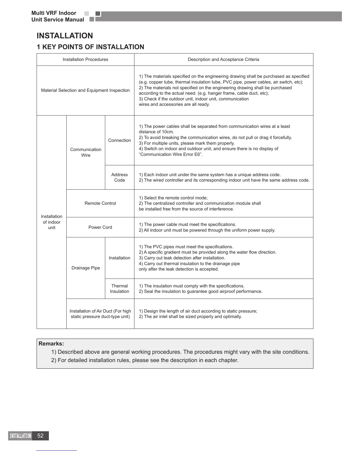
Installation Procedures Description and Acceptance Criteria
Material Selection and Equipment Inspection
(e.g. copper tube, thermal insulation tube, PVC pipe, power cables, air switch, etc);
according to the actual need. (e.g. hanger frame, cable duct, etc);
3) Check if the outdoor unit, indoor unit, communication
wires and accessories are all ready.
Installation
of indoor
unit
Communication
Wire
Connection
1) The power cables shall be separated from communication wires at a least
distance of 10cm.
2) To avoid breaking the communication wires, do not pull or drag it forcefully.
3) For multiple units, please mark them properly.
4) Switch on indoor and outdoor unit, and ensure there is no display of
“Communication Wire Error E6”.
Address
Code
1) Each indoor unit under the same system has a unique address code.
2) The wired controller and its corresponding indoor unit have the same address code.
Remote Control
1) Select the remote control mode;
2) The centralized controller and communication module shall
be installed free from the source of interference.
Power Cord
2) All indoor unit must be powered through the uniform power supply.
Drainage Pipe
Installation
3) Carry out leak detection after installation.
4) Carry out thermal insulation to the drainage pipe
only after the leak detection is accepted.
Thermal
Insulation
2) Seal the insulation to guarantee good airproof performance.
Installation of Air Duct (For high
static pressure duct-type unit)
1) Design the length of air duct according to static pressure;
2) The air inlet shall be sized properly and optimally.
Remarks:
1) Described above are general working procedures. The procedures might vary with the site conditions.
2) For detailed installation rules, please see the description in each chapter.

 Loading...