Installation
4.11 Wiring of the 2-Way Valve
The 2-way valve 1 is required to control water flow for cooling or heating operation. The role of 2-way
valve 1 is to cut off water flow into the underfloor loop when the fan coil unit is equipped for cooling
operation.
General Information
(1) Normal Open type. When electric power is NOT supplied, the valve is open. (When electric
power is supplied, the valve is closed.)
(2) Normal Closed type. When electric power is NOT supplied, the valve is closed. (When electric
power is supplied, the valve is open.)
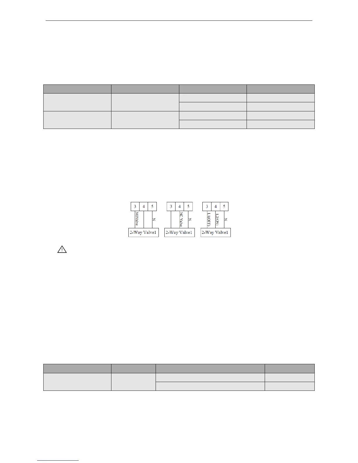
How to Wire 2-Way Valve:
Follow steps below to wire the 2-way valve.
Step 1. Uncover the front cover of the unit and open the control box.
Step 2. Find the terminal block and connect wires as below.
WARING!
(1) Normal Open type should be connected to wire (OFF) and wire (N) for valve closing in cooling
mode.
(2) Normal Closed type should be connected to wire (ON) and wire (N) for valve closing in cooling
mode.
(ON): Live signal (for Normal Open type) from PCB to 2-way valve
(OFF): Live signal (for Normal Closed type) from PCB to 2-way valve
(N): Neutral signal from PCB to 2-way valve
4.12 Wiring of the 3-Way Valve
The 3-way valve 2 is required for the sanitary water tank. Its role is flow switching between the under
floor heating loop and the water tank heating loop.
General Information
(1) SPDT = Single Pole Double Throw. Three wires consist of Live1 (for selecting Flow B), and
Neutral (for common).
(2) Flow A means 'water flow from the indoor unit to under floor water circ uit.
(3) Flow B means 'water flow from the indoor unit to sanitary water tank.

 Loading...