Unit Control
1 Integral Control Concept
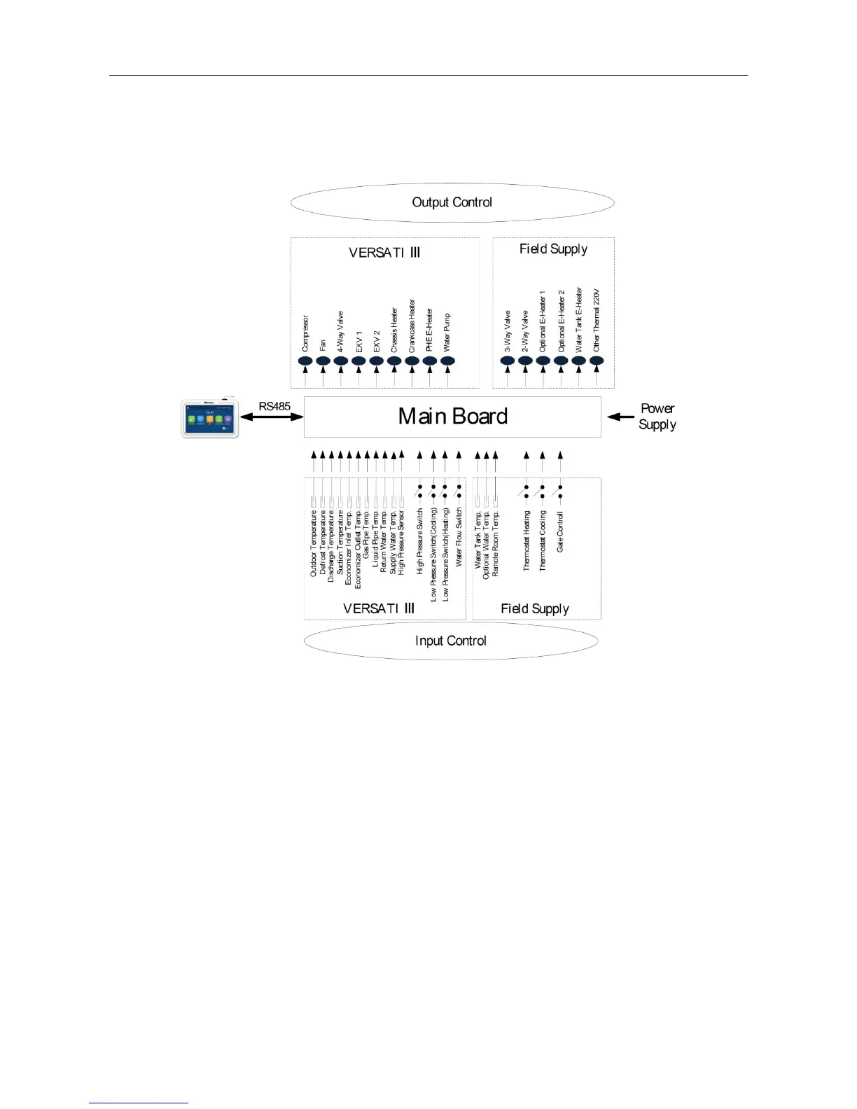
1.1 Control Principle Diagram
1. The outdoor temperature is detected by the sensor installed at fins of the finned heat exchanger,
which is mainly used to control the initialization steps of the fan and the electrostatic expansion valve
and also limit the maximum running frequency of the compressor. When this sensor fails, the main board
will detect it and deliver this error message to the controller and then the unit will fail to start up or shut
down.
2. The defroste temperature is detected by the sensor installed at the defrosting pipes of the finned
heat exchanger, which is mainly used to control defrosting. When this sensor fails at the heating or water
heating mode, the compressor will stop and this error will be displayed at the controller. When it fails at
the cooling mode, the compressor continues to run but this error will be displayed at the controller.
3. The discharge temperature is detected by the sensor installed at the discharge pipe of the
compressor, which is mainly used for high discharge temperature protection. When this sensor fails, this
error will be displayed at the controller, all loads except the water pump of the solar system and the
electric heater of the water tank will stop. Then, the main unit will resume normal running when this error
is eliminated.
4. The suction temperature is detected by the sensor installed at the suction pipe of the compressor,
which is mainly used to control superheating degree. When this sensor fails, this error will be displayed
at the controller, all loads except the water pump of the solar system and the electric heater of the water

 Loading...