Unit Control
t (design temperature): generally it is 60°C ;
t (entering cold water temperature): it differs for different regions;
t ( water tank temperature set point): it is the target heating temperature of the water tank.
α: correction factor
Empirical Values for Volume Correction of the Water Tank
Empirical values are worked out under conditions of 80L consumption (per day per person), 8L/min
flow rate of the shower head, and 10 minutes use duration per person.
7 Examples for Model Selection
7.1 General Introduction to the Example Project
For a two-floor house, there is a master room and a both room for each floor and both of them require
floor heating. Other rooms use the heat pump for heating in winter. The master room covers 28m
2
and
the both room covers 12m
2
.
7.2 Heat Load Calculation
7.2.1 Load Calculation of a Single Floor
7.2.2 Arrangement Design of the Underfloor System for A Single Floor
Assumed conditions: the floor is cement or ceramics, the normal external diameter of the heating pipe
is 20mm, thickness of the stuffer is 50mm, thickness of PS foam insulation is 20mm, supply water
temperature is 45°C, return water temperature is 35°C, indoor design temperature is 20°C.
Average Temperature of the Heating Pipe=(45+35)/2=40°C
7.2.3 Arrangement Design of the Underfloor System for the Bath Room
Heat load of the bath room is 900W, heat dissipation per unit area is 75W/m
2
, tube spacing of the heat
pipe is 30mm, and heat loss is 25.4 W/m
2
, then the total heat loss is:
25.4×12=304.8W
Based on the heat load listed in the table above, the heating load for the bathroom is:
900+304.8=1204.8W
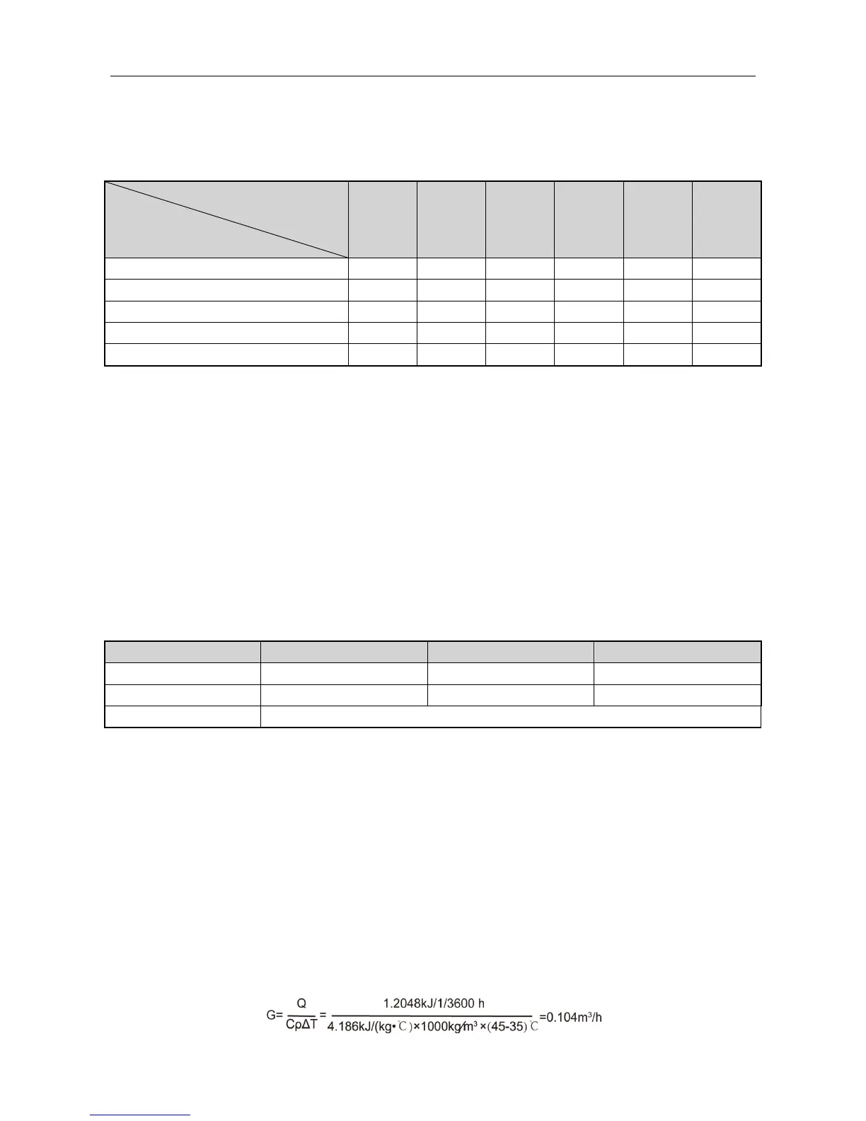
According to the formula Q=CρGΔT, the flow rate of the heating pipe for the bathroom is:

 Loading...