Do you have a question about the Hantek DSO2000 Series and is the answer not in the manual?
| Sample Rate | 1GSa/s |
|---|---|
| Math | +, -, *, /, FFT |
| FFT Window | Hanning, Hamming, Blackman, Rectangular |
| Power Supply | 100-240VAC, 50/60Hz |
| Real-Time Sample Rate | 1GSa/s |
| Bandwidth | 200 MHz |
| Display | 7-inch TFT LCD |
| Trigger Modes | Edge, Pulse, Video, Slope |
| Vertical Sensitivity | 2mV/div |
| Interface | USB host, USB device |
| Automatic Measurement | Vpp |
| Input Impedance | 1MΩ ± 2% |
Checks shipping container, accessories, and instrument for damage and completeness.
Steps for adjusting supporting legs and connecting the power cord for operation.
Introduces the front and back panels of the digital oscilloscope.
Explains the front operation panel, including display elements and indicators.
Steps to connect the oscilloscope and probe for a basic functional test.
Instructions to view a square wave using the Auto Set function.
Safety precautions to avoid electric shock when using the probe.
Procedure to adjust probe compensation for accurate measurements.
How to set probe attenuation to match oscilloscope settings.
Describes the function of various menu keys, operation mode keys, and shortcut keys.
Explains vertical controls like CH1/CH2 menu, Math Menu, Position, and Volts/Div.
Details horizontal controls like Horiz Menu, Position, and Sec/Div.
Introduces the trigger system controls like Trig Menu and Force Trig.
Describes signal source options like EXT TRIG/WAVE GEN and BURST/GEN TRIG.
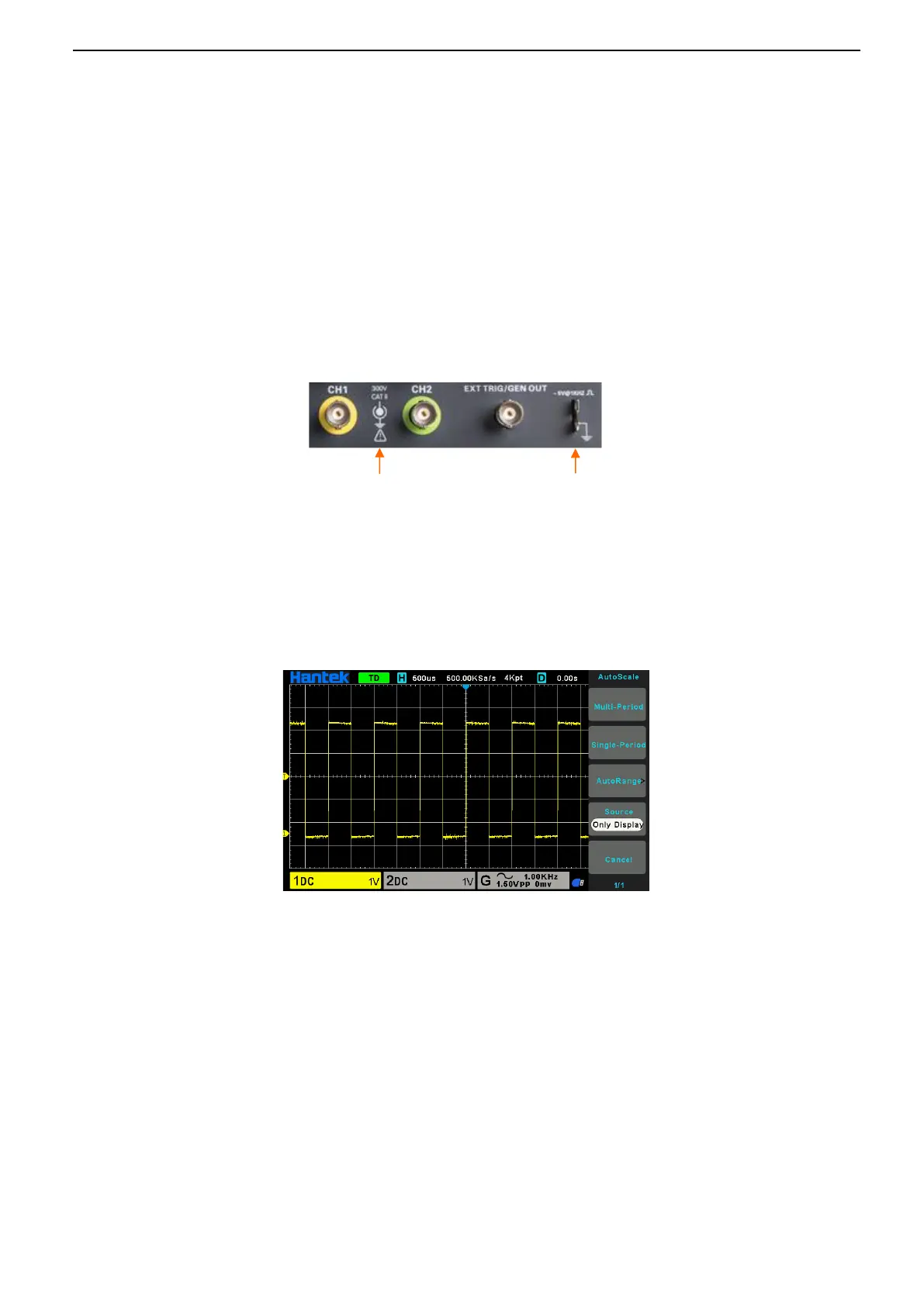
Details the function of CH1, CH2, and EXT TRIG/GEN OUT connectors.
Explains the operation of the multifunctional knob (VO) and softkeys.
Automatically adjusts controls for a stable waveform display.
How to save the current oscilloscope settings.
How to recall saved or default factory setups.
Resets the oscilloscope to its factory default configuration.
Controls trigger position relative to the screen center.
Adjusts horizontal time scale to magnify or compress waveforms.
Details vertical controls for display, scale, position, and input parameters.
Explains how to perform math operations like addition, subtraction, multiplication, division, and FFT.
Defines available sources for triggering the oscilloscope.
Explains Auto and Normal modes for data acquisition.
Sets horizontal position relative to the trigger point.
Sets the amplitude level for triggering.
Triggers based on specified edge (rising, falling) and trigger level.
Triggers on positive or negative pulses of a specified width.
Captures complex analog video signals using NTSC or PAL standards.
Triggers based on rising or falling transition time within a specified range.
Triggers when the time interval between edges exceeds a set timeout.
Triggers when the signal passes through high or low trigger levels.
Triggers based on a specified logical pattern of channel states.
Triggers when the time difference between edges meets a time condition.
Triggers on pulses crossing one threshold but not another.
Triggers based on UART serial communication parameters like baud rate and parity.
Triggers on LIN bus signals like Sync Break, Frame ID, or ID and Data.
Triggers on CAN bus frames based on start bit, frame ID, or data.
Triggers on SPI bus data when specified data is found or timeout occurs.
Triggers on IIC bus signals based on start/stop conditions, address, or data.
Interprets and displays UART serial data on the waveform.
Interprets and displays LIN bus serial data on the waveform.
Interprets and displays CAN bus serial data on the waveform.
Interprets and displays SPI bus serial data on the waveform.
Interprets and displays IIC bus serial data on the waveform.
Describes saving and recalling setups, waveforms, and references internally.
Steps to save the current oscilloscope setup to internal memory.
Steps to recall a setup file from internal memory.
Procedures for saving and recalling files to/from external USB storage.
Saving screenshots to an external USB storage device.
Manages files and folders on external storage, including creating new ones.
Using graticule divisions and scale factor for visual measurement estimation.
Using cursors (amplitude/time) in manual or tracking modes for measurement.
Performing automatic calculations of waveform parameters for precision.
Digital Voltmeter function for voltage and frequency measurements.
Controls for running, stopping, or capturing single-shot waveforms.
Details Normal, Peak Detect, Average, and High Resolution acquisition modes.
Displays voltage of CH1 vs CH2, used for phase difference analysis.
Waveform display scrolls from right to left, no trigger control.
Settings for display type, intensity, grid, brightness, and persistence.
Settings for display language and buzzer configuration.
Updates the oscilloscope firmware using a USB disk.
Routine to optimize signal path accuracy, recommended for temperature changes.
Sets up signal input judging rules and outputs pass/fail status.
Automatically adjusts controls for usable input signal display.
Captures a single waveform and stops acquisition.
Continuously acquires waveform or stops acquisition.
Recalls the oscilloscope to its default settings.
Identifies waveform type and adjusts controls for accurate display.
Resets oscilloscope to default settings, including CH1 waveform display.
Allows viewing two different time bases or zoomed sections simultaneously.
Sets waveform type, frequency, amplitude, duty cycle, and symmetry.
Configures amplitude and frequency modulation for generated waveforms.
Sets the number of pulses and data source for burst output.
Using WaveEditor software to create and manage arbitrary waveforms.
Downloading arbitrary waveforms from PC to the oscilloscope.
Instructions for installing the necessary IO driver for remote control.
Steps to troubleshoot power-on issues, checking power cord and button.
Troubleshooting steps for no waveform display, checking probes, channels, and signals.
Steps to diagnose distorted waveforms, checking probe connection and calibration.
Troubleshooting unstable waveforms that are not triggered.
Information on contacting local distributors for support.
Information on contacting local field offices for support.
Contact details for HANTEK headquarters.
Precautions for device placement and avoiding damage from liquids/solvents.
Instructions for cleaning the oscilloscope and probes with lint-free cloths.
Detailed specifications for horizontal system parameters.
Detailed specifications for vertical system parameters.
Specifications related to sample rate, acquisition modes, and memory depth.
Specifications for various trigger types like Edge, Pulse, Video, Slope, etc.
Trigger specifications for under amplitude conditions.
UART trigger specifications including condition, data format, and baud rate.
LIN trigger specifications including condition, data format, and baud rate.
CAN trigger specifications including condition, data format, and baud rate.
SPI trigger specifications for data format and length.
IIC trigger specifications for data format and index.
Specifications for input channels, coupling, impedance, attenuation, and voltage limits.
Specifications for cursors, automatic measurements, and DVM.
Specifications for math operations like +, -, *, /, FFT.
Specifications for saving/recalling files and external storage.
Specifications for arbitrary waveform generation, including standard waveforms and modulation.