12 / 72
1.6.2. Manual Probe Compensation
Upon the first connection of a probe and an input channel, you should manually perform this
adjustment to match the probe to the input channel. Uncompensated or miscompensated probes may
lead to errors or faults in measurement. To adjust the probe compensation, follow the steps below.
1. Set the Probe option attenuation in the channel menu to 10X. Set the switch on the probe to 10X and
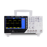
connect the probe to Channel 1 on the oscilloscope. If you use the probe hook-tip, ensure it is firmly
inserted onto the probe. Attach the probe tip to the PROBE COMP ~2V@1KHz connector and the
reference lead to the PROBE COMP Ground connector. Display the channel and then press the Auto
Scale button.
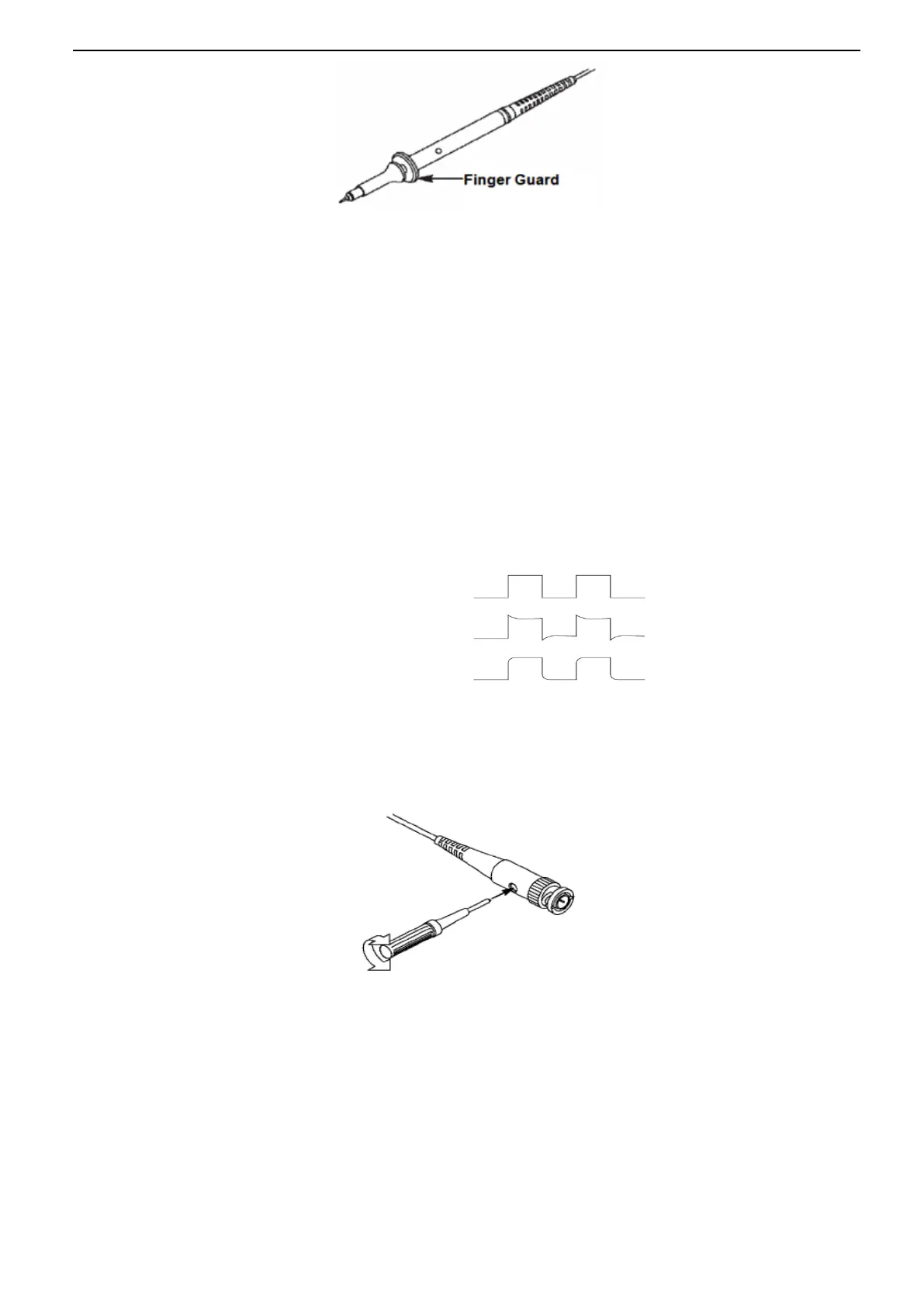
2. Check the shape of the displayed waveform.
3. If necessary, use a nonmetallic screwdriver to adjust the variable capacity of your probe until the
shape of the waveform turns to be the same as the above figure. Repeat this step as necessary. See the
figure below for the way of adjustment.
1.6.3. Probe Attenuation Setting
Probes are of various attenuation factors which affect the vertical scale of the signal. The Probe Check
function is used to verify if the Probe attenuation option matches the attenuation of the probe.
You can push a vertical menu button (such as the CH1 MENU button) and select the Probe option that
matches the attenuation factor of your probe.
Compensated correctly
Overcompensated

 Loading...