3 - Description
3.6
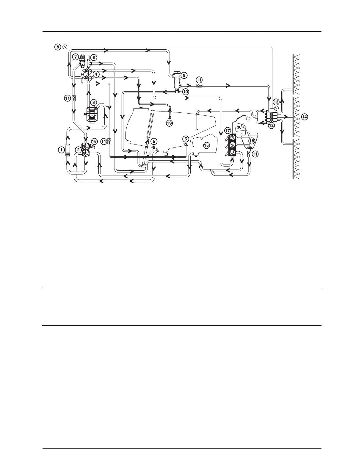
Diagram - Diaphragm Liquid system
Control unit
EVC - Electrical Valve Control. The ON/OFF is linked to the section valves, which results in a very quick response to ON/OFF.
The operating unit is constructed of modules and is electrically controlled via a remote control box. The unit is fit with built-
in HARDI-MATIC.
Filters
In-line pressure filters are fitted at each section. A suction filter can also be fitted under the platform.
All filters should always be in use and their function checked regularly. Pay attention to the correct combination of filter
mesh size. The mesh size should always be less than the flow average of the nozzles in use.
1. Suction filter (optional)
2. Suction manifold
3. Pump
4. Pressure manifold
5. Agitation
6. Safety valve
7. HARDI-MATIC
8. Remote system pressure gauge
9. CycloneFilter
10. Off/On/Purge valve
11. Check valves
12. Boom section valves
13. System pressure gauge
14. Boom
15. Flush tank (optional)
16. Quick fill
17. Valve block TurboFiller (optional)
18. TurboFiller (optional)
19. Tank rinse nozzle (optional)
 Loading...