Pomona, CA Clemmons, NC Nashville, TN
Tel: 908-351-5400 www.haywardpool.com
USE ONLY HAYWARD GENUINE REPLACEMENT PARTS
11
$#:%+A&B!+*.!*.%+./]
/RFDWHWKHSRROVSDKRWWXEKHDWHULQDQDUHDZKHUHOHDNDJHRIWKHKHDWH[FKDQJHURUFRQQHFWLRQVZLOOQRW
result in damage to the area adjacent to the heater or to the structure. When such locations cannot be avoided,
it is recommended that a suitable drain pan, with drain outlet, be installed under the heater. The pan must not
UHVWULFWDLUÀRZ
7KLVKHDWHUPXVWEHLQVWDOOHGDWOHDVWIHHWIURPWKHLQVLGHZDOORIDSRROLQJURXQGRUDERYHJURXQG
VSDKRWWXEXQOHVVVHSDUDWHGIURPWKHSRROVSDKRWWXEE\DVROLGEDUULHU
The heater must be installed such that the location of the exhaust gas vent assembly outlet relative to
adjacent public walkways, adjacent buildings, openable windows, and building openings complies with the
1DWLRQDO)XHO*DV&RGH$16,=1)3$DQGRU&$1&*$%LQVWDOODWLRQFRGHV2XWGRRULQVWDO-
lation and service clearances:
The heater must be installed outdoors such that the installation and service clearances from combustible
PDWHULDOVVKRZQLQ7DEOHDUHPDLQWDLQHG7KLVKHDWHUPD\EHLQVWDOOHGRQFRPEXVWLEOHÀRRUV
1. The heater is self-venting when installed outdoors and does not require additional vent piping.
2. Do not install in a location where growing shrubs may in time obstruct a heater’s combustion air
and venting areas.
3. Do not install this appliance under an overhang less than (3) feet from the top of the appliance.
The area under the overhang must be open on (3) sides.
4. Do not install the heater where water spray from ground sprinkler can contact the heater. The wa-
ter could splash on the controls causing electrical damage.
5. Do not install under a deck.
,&:/%+A&B!+*.!*.%+./]
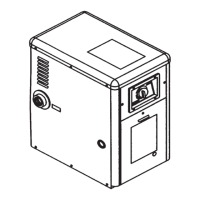
To remove the shipping carton from the heater:
1. Remove the corrugated carton from the
heater. The carton, top pad, bottom pad, and
the four corner posts can be recycled.
2. There are three (3) screws total used to se-
cure the heater to the wood pallet. All three
must be removed to separate the heater from
the pallet. One (1) is located in the lower
rear of the heater as shown in Figure 1.
3. To access the other two (2) screws, open the
front access panel by removing the four (4)
black phillips-head screws. Then remove
the two (2) screws which hold the
heater base pan to the pallet as
shown in Figure 2.
4. Lift the heater clear of the corrugat-
ed bottom pad and off of the pallet.
ATTENTION: Do not drop the
heater from a pickup truck tailgate
to the ground. This may damage the
heater.
Remove the (2)
shipping screws
and discard bottom
corrugated tray.
Figure 2
Figure 1
The screw through the
rear shipping bracket
is located in this area.
Remove the screw.
It is not necessary to
remove the bracket or
the rear louvered panel.

 Loading...