Pomona, CA Clemmons, NC Nashville, TN
Tel: 908-351-5400 www.haywardpool.com
USE ONLY HAYWARD GENUINE REPLACEMENT PARTS
28
'/%A&!Q%$Q.!A&(+%$$%+A#&!_%(9.!9#'.$(!#&$U`]
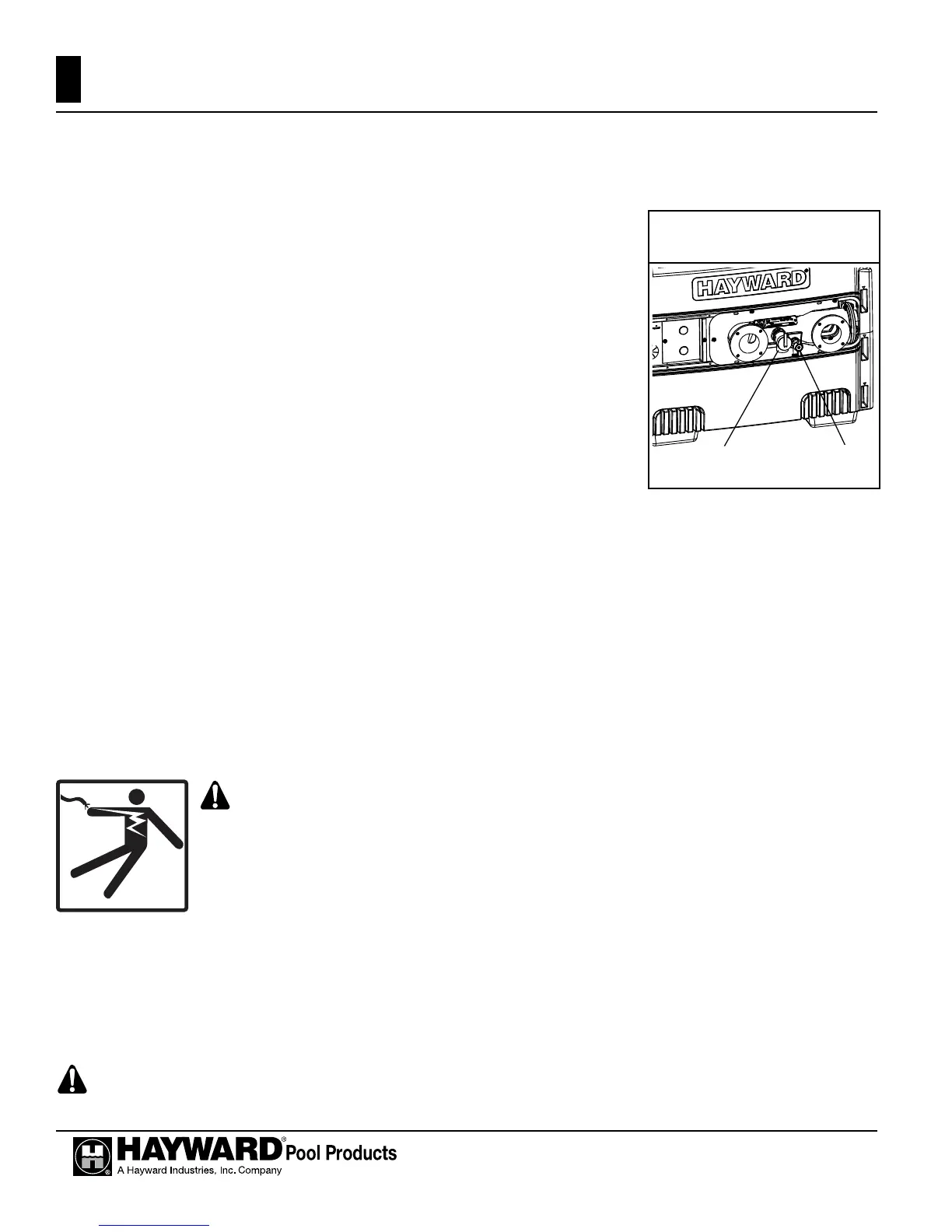
,ILQVWDOOLQJDQ$60(PRGHOKHDWHUD´EUDVVGUDLQYDOYHPXVWEHLQVWDOOHG$VXLWDEOHGUDLQYDOYHLV
LQFOXGHGVHSDUDWHO\ZLWKDOO$60(KHDWHUV$SSO\DVXLWDEOHDPRXQWRISLSHWKUHDGVHDODQWRUWHÀRQWDSHWR
the threads and install as shown in Figure 21.
"/.((,/.!/.$A.3!Q%$Q.!_%(9.!9#'.$(!#&$U`]
,ILQVWDOOLQJDQ$60(PRGHOKHDWHUD´SUHVVXUHUHOLHIYDOYHKDYLQJD
GLVFKDUJHFDSDFLW\JUHDWHUWKDQRUHTXDOWRWKH%WXKULQSXWRIWKHKHDWHUDQGD
pressure rating equal to or less than the working pressure must be installed. See
the rating plate located inside the front access panel on the heater for the input
rating and working pressure. A suitable pressure relief valve is included sepa-
rately with all ASME heaters. Apply a suitable amount of pipe thread sealant or
WHÀRQWDSHWRWKHWKUHDGVDQGLQVWDOODVVKRZQLQ)LJXUH3OHDVHQRWHWKDWWKH
drain valve must be installed before the pressure relief valve. Install the pressure
relief valve with the discharge connection facing the ground. If necessary, con-
nect a pipe (of the same size as the valve outlet) to the outlet and run it to a safe
place of discharge. Do not install any shut-off or restriction in this drain line.
"/.((,/.!/.$A.3!Q%$Q.!_&#&N%(9.!9#'.$(!#&$U`]
6RPHORFDOEXLOGLQJFRGHVUHTXLUHDSUHVVXUHUHOLHIYDOYHIRUQRQ$60(SRROVSDKHDWHUV7KHSODVWLFKHDGHU
KDVD´SRUWZKLFKFDQEHXVHGIRUWKLVSXUSRVHVHH)LJXUHIRUORFDWLRQRISRUW$´SUHVVXUHUHOLHI
YDOYHKDYLQJDGLVFKDUJHFDSDFLW\JUHDWHUWKDQRUHTXDOWRWKH%WXKULQSXWRIWKHKHDWHUDQGDSUHVVXUHUDWLQJ
equal to or less than the working pressure is recommended. See the rating plate located inside the front access
panel on the heater for the input rating and working pressure. If desired, you may order the pressure relief valve
IURP+D\ZDUGRUGHUSQ&+;5/95HPRYHWKHIDFWRU\LQVWDOOHGSLSHSOXJDQGLQVWDOOWKHSUHVVXUHUHOLHI
YDOYHXVLQJDVXLWDEOHDPRXQWRISLSHWKUHDGVHDODQWRUWHÀRQWDSHRQWKHWKUHDGV,QVWDOOWKHSUHVVXUHUHOLHIYDOYH
with the discharge connection facing the ground. If necessary, connect a pipe (of the same size as the valve out-
let) to the outlet and run it to a safe place of discharge. Do not install any shut-off or restriction in this drain line.
.$.:+/A:%$!(".:A3A:%+A#&(!]
WARNING: It is required that licensed electricians do all electrical wiring. Risk
of Electric Shock. Hazardous voltage can shock, burn, and cause death or serious
property damage. To reduce the risk of electric shock, do NOT use an extension cord
to connect unit to electric supply. Provide a properly located electrical receptacle. All
electrical wiring MUST be in conformance with applicable local and national codes
and regulations. Before working on heater, turn off power supply.
B.&./%$!A&3#/9%+A#& ]
Wiring connections must be made as shown in the wiring diagram found inside the heater cabinet, and as
VKRZQLQ)LJXUH7KHKHDWHUPXVWLQFOXGHDGH¿QLWHPHDQVRIJURXQGLQJDQGERQGLQJ7KHUHLVDJURXQG
lug inside the control box and a bonding lug on the side of the heater.
9%A&!"#V./ ]
WARNING - Power connections supplied to the heater must be in accordance with National Electric
Figure 21: Drain valve and
relief valve locations
Pressure
Relief Valve
Drain
Valve

 Loading...