Pomona, CA Clemmons, NC Nashville, TN
Tel: 908-351-5400 www.haywardpool.com
USE ONLY HAYWARD GENUINE REPLACEMENT PARTS
/.9#+.!:#&+/#$!:#&&.:+A#&]
The heater is equipped for con-
nection to an external 2-wire remote
thermostat or a 3-wire remote switch. A
2-wire thermostat has its own tempera-
ture sensor for regulating water tempera-
ture. A 3- wire remote switch allows the
³322/´RU³63$´PRGHOVWREHUH-
PRWHO\VHOHFWHG&RQQHFWUHPRWHZLULQJ
to the terminal block located in the lower
compartment inside the junction box (see
Figure 22). The heater has 2 junction
boxes (one on each side of the heater).
Only one junction box should be used for
remote wiring. Do not remove the wires
connected to the remote connection ter-
minal block. Remote wiring must be run
LQDVHSDUDWHFRQGXLW8VH$:*ZLUH
IRUUXQVOHVVWKDQIHHW8VH$:*
wire for runs over 30 feet. The maximum
allowable run is 200 feet.
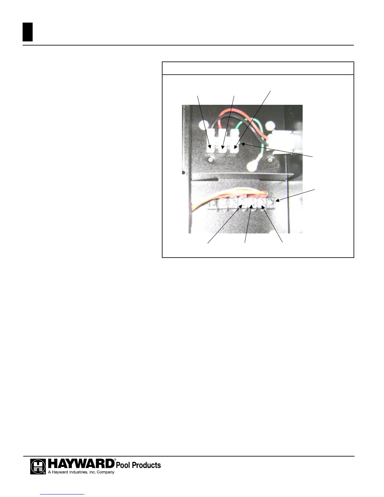
Figure 22
5NVA/.!/.9#+.!:#&+/#$!:#&&.:+A#&]
7RFRQ¿JXUHWKHKHDWHUIRUZLUHUHPRWHWKHUPRVWDWFRQWUROXVHWKH³02'(´NH\RQWKHKHDWHUNH\SDG
WRSXWWKHFRQWUROLQWR³67$1'%<´PRGH7KHQSUHVVDQGKROGERWKWKH³'2:1´DQG³02'(´NH\VIRU
VHFRQGVXQWLOWKHGLVSOD\VKRZVWKHFRGH³ER´
On the remote control wiring terminal block (Figure 22), connect the appropriate wires from the remote
FRQWUROWRWKHWHUPLQDOVDGMDFHQWWRWKH25$1*(ZLUH³322/´DQG:+,7(ZLUH³9´
7RRSHUDWHWKHKHDWHUE\UHPRWHWKHUPRVWDWWKHKHDWHU¶VFRQWUROPXVWEHLQHLWKHU³322/´RU³63$´
PRGH7KHGLVSOD\ZLOOVKRZ³ER´7KH³322/´RU³63$´/('ZLOOEHLOOXPLQDWHG7KHUHPRWHWKHUPRVWDW
will operate the heater. The heater’s thermostat will function to limit the water temperature to a maximum of
Ĉ)
6NVA/.!/.9#+.!:#&+/#$!:#&&.:+A#&]
On the remote control wiring terminal block (Figure 22), connect the appropriate wires from the remote
FRQWUROWRWKHWHUPLQDOVDGMDFHQWWRWKH25$1*(ZLUH³322/´:+,7(ZLUH³9´DQG5('ZLUH
³63$´7RRSHUDWHWKHKHDWHUZLWKDUHPRWHZLUHVZLWFKWKHKHDWHU¶VFRQWUROPXVWEHLQ³67$1'%<´
PRGH7KH³67$1'%<´/('ZLOOEHLOOXPLQDWHG:KHQWKHUHPRWHVZLWFKLVVHWWR³3RRO/RZ´WKH³322/´
LED will be illuminated and the water WHPSHUDWXUHZLOOEHGLVSOD\HG:KHQWKHUHPRWHVZLWFKLVVHWWR³6SD
+LJK´WKH³63$´/('ZLOOEHLOOXPLQDWHGDQGWKHZDWHUWHPSHUDWXUHZLOOEHGLVSOD\HG7KHKHDWHUZLOOXVHLWV
internal thermostat to regulate the water temperature to the set point of the mode selected.
Spa (RED)
Common
Pool
Remote
Connection
Terminal Block
L (120v)
or
L1 (240v)
N (120v)
or
L2 (240v)
Ground
Field Power
Wiring Terminal
Block
30

 Loading...