Chapter 2 System Wiring
The preparaon before installaon and general wiring.
Steps
1. Draw a central line on the
installaon surface of the le or right pedestal.
2. Draw other parallel lines for installing the other pedestals.
Note
The distance between the nearest two line is L+200 mm. L represents the lane width.
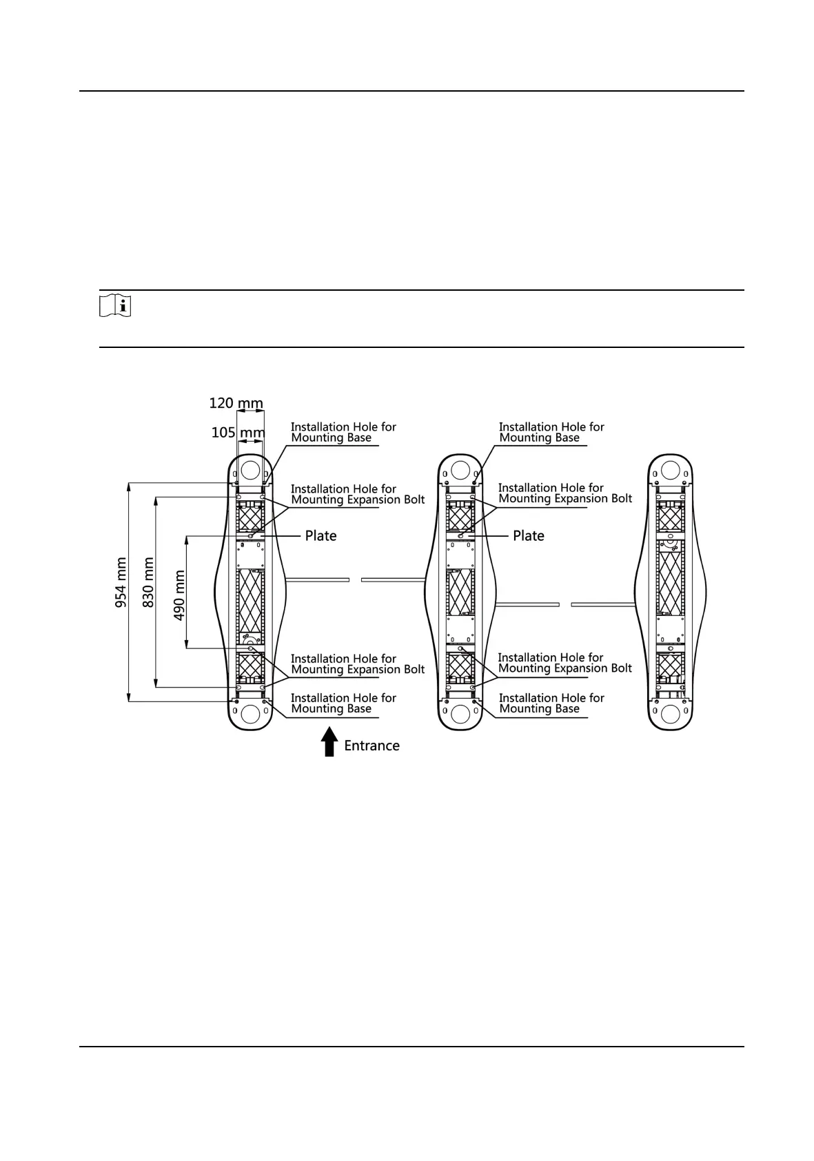
3. Slot on the installaon surface and dig installaon holes according to the hole posion diagram.
Figure 2-1 Hole Posion Diagram
4. Bury cables. Each lane buries 1 network cable and 1 high voltage cable. For details, see the
system wiring diagram below.
DS-K3Y411X Series Flap Barrier Quick Start Guide
3
 Loading...